
Sequential timer
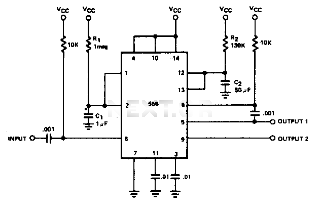
The described circuit employs a dual timer, typically a 555 timer IC, to create a sequential timing mechanism. The first half of the timer operates in monostable mode, generating a time delay ti based on the values of resistor R1 and capacitor C1. When the circuit is powered, a momentary connection of pin 6 to ground triggers the timer, causing it to output a high signal for a duration defined by the time constant τ1 = R1 × C1.
The output from the first half is then fed into the second half of the timer through a 0.1 µF coupling capacitor. This capacitor serves to block any DC offset while allowing the timing pulse to pass through, effectively triggering the second half of the timer. The second half operates similarly in monostable mode, with its timing determined by resistor R2 and capacitor C2, resulting in a delay ta.
This configuration allows for a precise control of timing sequences in various applications, such as in flashing LEDs, pulse generation, or timed events in control systems. The selection of R1, C1, R2, and C2 values will define the specific timing intervals, enabling customization for different operational requirements. The circuit can be further enhanced by adding additional components such as diodes for protection, or transistors for driving higher loads, depending on the intended application.By utilizing both halves of a dual timer it is possible to obtain sequential timing. By connecting the output of the first half to the input of the second half via a 01 µF coupling capacitor sequential timing may be obtained. Delay ti is determined by the first half and ta by the second half delay. The first half of the timer is started by momentarily connecting pin 6 to ground When it is turned out (determined by 1R1C1), the second half begins. Its duration is determined by 1R2C2. 🔗 External reference
Related Circuits
AT89S52 for Bell Timer Circuit Diagram. Features: 7-segment display is replaced with LCD display. DS1307, uses AT89S52 microcontroller and I2C. The circuit utilizes the AT89S52 microcontroller, which is an 8-bit microcontroller from the Atmel 8051 family. This microcontroller is programmed...
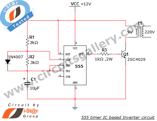
This article explains what an inverter is and how to construct a simple, low-cost 12V to 220V inverter circuit. An inverter functions as a DC to AC converter and is a valuable electronic product for compensating for emergency power...
The 555 timer IC was first introduced around 1971 by the Signetics Corporation as the SE555/NE555 and was referred to as "The IC Time Machine." It was the first commercially available timer IC, providing circuit designers and hobbyists with...
A programmable clock timer circuit that utilizes individual LEDs to indicate hours and minutes. Twelve LEDs can be arranged in a circle to represent the twelve hours of a clock face, while an additional twelve LEDs can be arranged...
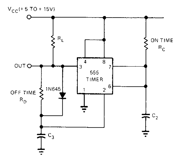
The 555 timer circuit has unsteady open and closing times that are independent of one another. One time constant is given by 1.1RcC2, while another time constant is defined as 1.1RcC3. The free-running period is the sum of these...

This circuit turns off an amplifier or any other device when a low-level audio signal fed to its input is absent for at least 15 minutes. By pressing P1, the device is powered on, supplying power to any appliance...