
555 Timer astable oscillator circuit
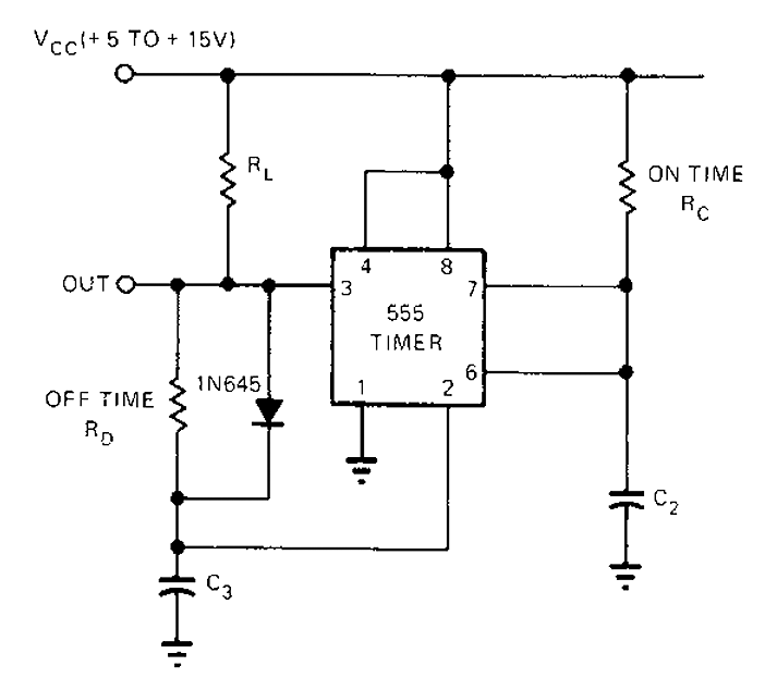
The 555 timer is a versatile integrated circuit used in various timing applications, including oscillators, pulse generation, and time delay circuits. In this configuration, the circuit operates in astable mode, producing a continuous square wave output. The independent time constants, defined by the resistors (R) and capacitors (C), determine the duration of the high and low states of the output signal.
The first time constant, 1.1RcC2, represents the time taken for the capacitor C2 to charge through the resistor R, reaching approximately 66.7% of the supply voltage (Vcc). Conversely, the second time constant, 1.1RcC3, reflects the time taken for the capacitor C3 to discharge through the same resistor R, dropping to about 33.3% of Vcc. The independence of these time constants allows for flexible control over the duty cycle of the output waveform.
The free-running period (th) of the 555 timer in this configuration is the sum of the two time constants, which can be expressed mathematically as:
th = 1.1RcC2 + 1.1RcC3.
This relationship is critical for applications requiring precise timing and control, as it allows for the adjustment of the frequency and duty cycle by varying the values of the resistors and capacitors. By selecting appropriate component values, designers can tailor the output waveform to meet specific requirements, making the 555 timer an essential tool in electronic circuit design.555 timer circuit unsteady open and closing times are independent of each other. Wherein a time constant is 1.1RcC2, another time constant is 1.1RcC3. Free-running period is th e sum of these time constants.
Related Circuits
Xenon lamp, strobe light circuits, xenon strobe, photo flash, photoflash, schematics or diagrams, all free to use. The inspiration originated from a strobe circuit that was part of a school fire alarm. Xenon lamps are high-intensity discharge lamps that emit...
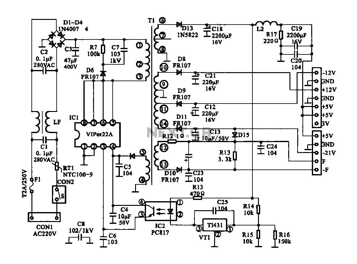
The Dragon ZL-2801A is a DVD machine that utilizes a switching power supply circuit. The circuit primarily consists of an AC input circuit, a rectifier filter wave circuit, an oscillation circuit switch, a switch transformer (Tl), a secondary rectifier,...
The pulser is designed to switch the mains voltage on and off at intervals ranging from just under one second to up to 10 minutes. This functionality is particularly useful for testing mains-operated equipment over extended periods or for...
Unlike conventional small-signal methods, employing large-signal, time-domain design techniques facilitates the development of low-noise grounded-base oscillators suitable for VHF/UHF applications. The implementation of large-signal, time-domain design techniques in the creation of grounded-base oscillators represents a significant advancement in the field...
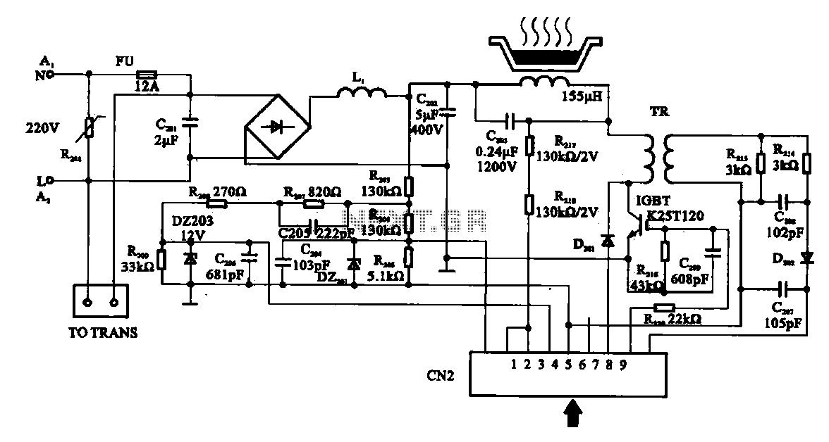
Cooker detection control circuit. The control circuit is designed for testing cookers. The inductance coil disc lesion typically measures around 150 µH. The stove plate coil and capacitor resonate with device C203. When resonating, the voltage generated across C203...
The primary objective is to present the circuit diagram and describe the software utilized. A UDP application is employed to transmit commands to the microcontroller, which subsequently activates or deactivates the relay. It is anticipated that TCP implementation could...