
Parking call alarm circuit
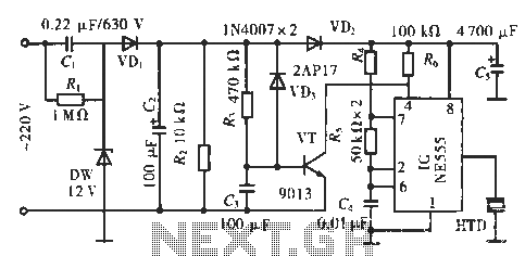
The circuit is designed to respond to incoming calls by utilizing the 555 timer IC in a monostable configuration. The 555 IC is a versatile component widely used in timer, delay, pulse generation, and oscillator applications. In this setup, the circuit begins with the application of 220 V AC, which is first reduced to a lower voltage using resistor R1. This resistor acts as a current-limiting component, ensuring that the subsequent components are not subjected to excessive voltage.
The rectification process is carried out by diode VD1, converting the AC voltage to a pulsating DC voltage. Following this, the voltage regulator (DW) stabilizes the voltage to a precise 12 V DC, which is crucial for the reliable operation of the 555 IC and other components in the circuit. Capacitor C2 plays a critical role in smoothing out the rectified voltage, filtering out any ripple that may affect the performance of the circuit.
When a call is received, the voltage across capacitor C3 affects the base of transistor VT. The design ensures that the base voltage drops to a low level, causing the transistor to enter cutoff mode. In this state, the collector of VT is pulled to a high potential, which is essential for maintaining the reset terminal (pin 4) of the 555 timer in a high state. This high state on pin 4 prevents the timer from triggering and allows the circuit to maintain its current operation until the call is processed.
Overall, this circuit effectively integrates power management and signal processing to respond to incoming calls, showcasing the functionality of the 555 timer IC in conjunction with basic electronic components.Circuit works: lC is a 555 IC. Incoming calls, 220 V electricity through R1 Buck, VD1 rectifier, DW regulator, C2 filtered to give 12 V DC voltage of about. When an incoming call, VT base due to voltage on C3 non-mutation showed low potential. VT cutoff, the collector is high potential, so that the reset terminal lC 4 feet high.
Related Circuits
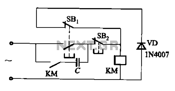
An AC contactor switch, when used with DC or pulse DC excitation, can minimize short circuit and core power consumption. This results in a significant reduction in the power consumption of the electromagnet, which can eliminate noise and reduce...
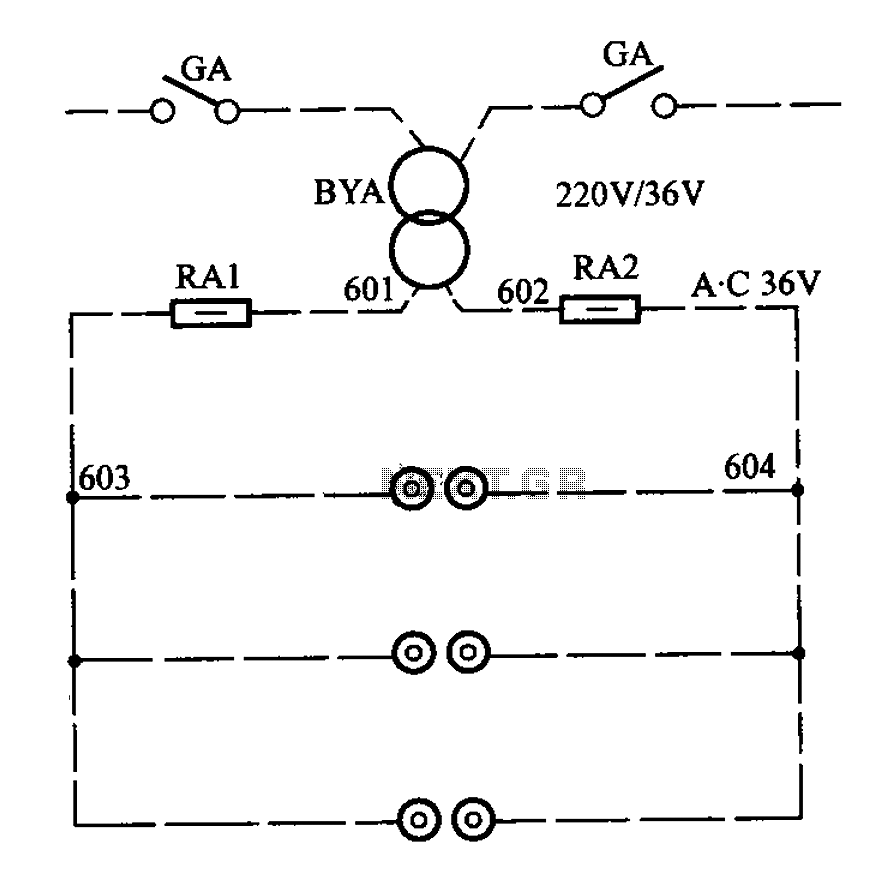
APM-81 lift includes the main circuit, safety circuit, and brake circuit. The APM-81 lift system is designed with a comprehensive electrical architecture that integrates a main circuit, a safety circuit, and a brake circuit, ensuring reliable operation and enhanced safety...
This circuit is a wireless car alarm system composed of two modules: a transmitter and a receiver. It operates using FM radio waves and is compatible with vehicles that have a 6-12V DC power supply. If the vehicle's power...
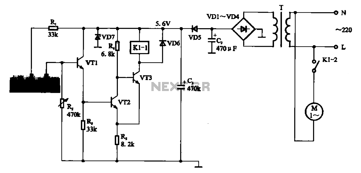
AC motor control circuit for a sprinkler. If the circuit involves an AC motor, it can be designed according to the connection shown in the figure, detailing the work process and the underlying principles of the circuit. The AC motor...
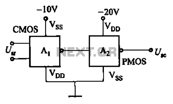
CMOS and PMOS cross interface circuit with PMOS integrated circuit providing high input impedance, allowing the input current to be negligible. The CMOS and PMOS interface circuit is illustrated in the accompanying figure. The CMOS and PMOS cross interface circuit...
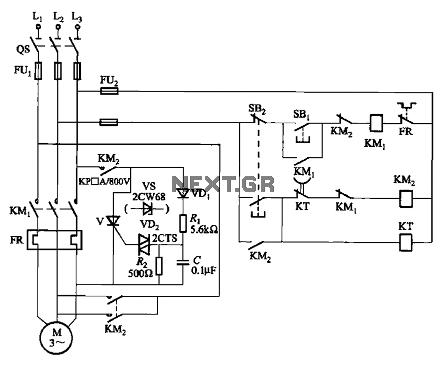
The circuit illustrated in Figure 3-148 eliminates the requirement for a step-down transformer by utilizing a thyristor for brake control in small capacity asynchronous motor braking applications. Upon shutdown, the contactor KM1 releases, while contactor KM2 engages the brake...