
Serial To Parallel Converter

The circuit design consists of a serial-to-parallel converter that interfaces a personal computer's serial port with a printer's parallel port. The primary function of the circuit is to convert a 2400 baud serial input signal into a parallel output compatible with Centronics printers. The circuit utilizes the TxD, CTS, and DSR lines from the RS232 serial port to facilitate communication and handshaking between the computer and the printer.
The MAX232 integrated circuit is essential for converting the TTL logic levels used by the serial port to the RS232 voltage levels required for proper communication. It takes the +5V supply from the computer and converts it to the ±12V levels necessary for RS232 signaling, ensuring reliable data transmission.
The programmed PIC controller (IC1) is the heart of the parallel conversion process. It interprets the incoming serial data stream and generates the corresponding Centronics-compatible parallel output. The controller is programmed to handle eight data bits, with no parity and one stop bit, which aligns with standard serial communication formats. Additionally, the controller generates control signals required for the operation of the Centronics interface, such as strobe and acknowledge signals.
To manage potential delays in the Centronics communication, the Flow signal (pin 17) can be used to pause the RS232 bitstream. This feature is crucial for preventing data loss during periods when the printer may not be ready to receive data.
The circuit also requires a 4 MHz ceramic resonator (X1) to provide the necessary clock signal for the PIC controller, ensuring accurate timing for data processing and output generation. Overall, this converter effectively bridges the communication gap between serial and parallel interfaces, allowing for seamless integration of serial devices with parallel printers.This converter may help if just the serial port on a personal computer is free, whereas the printer needs a parallel (Centronics) port. It converts a serial 2400 baud signal into a parallel signal. The TxD line, pin 3, CTS line, pin 8 and the DSR line, pin 6, of the serial port are used - see diagram.
The CTS and DSR signals enable handshaking to be implemented. Since the computer needs real RS232 levels, an adaptation from TTL to RS232 is provided in the converter by a MAX232. This is an integrated level converter that transforms the single +5V supply into a symmetrical ±12V one.
The serial-to-parallel conversion is effected by IC1. This is essentially a programmed PIC controller that produces a Centronics compatible signal from a 2400 baud serial signal (eight data bits, no parity, one stop bit). The IC also generates the requisite control signals. If there is a delay on the Centronics port, the RS232 bitstream from the computer may be stopped via the Flow signal (pin 17).
This ensures that no data is lost. The controller needs a 4 MHz ceramic resonator, X1. 🔗 External reference
Related Circuits
This document serves as a resource for developers who are new to Texas Instruments (TI) ARM-based processors, as well as for seasoned developers seeking to deepen their understanding of the different ARM architectures. It starts with an overview of...
This circuit is an oscillator at frequency 10MHZ, using IC 1A and IC1B and a frequency divider. Using the IC2 it divides the pulses to 10. IC1C is a buffer. The variable capacitor 39pF is microtuning the frequency. The...
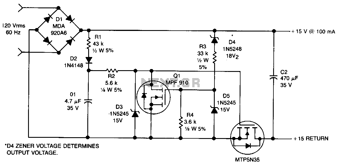
This non-isolated, unregulated converter with minimal components serves as a bridge between low-power zener regulation and the higher power applications of a 60-Hz input transformer. It is designed for scenarios where a non-isolated power supply can be utilized safely....
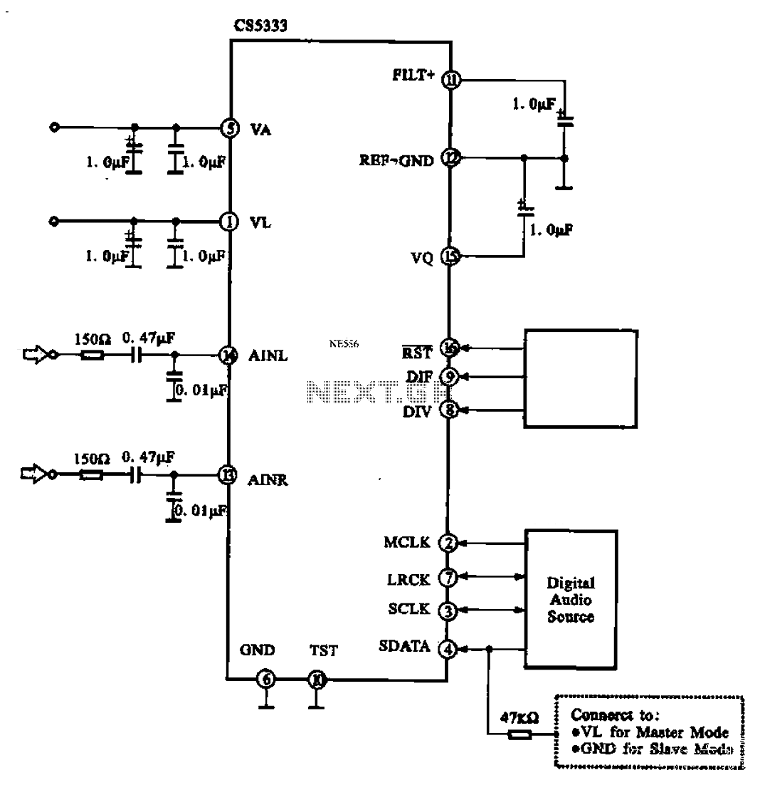
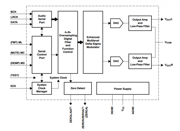
Audio A/D converter circuit configuration using the CS5333 chip, which is a high-performance 24-bit, 96 kHz stereo A/D converter commonly used in digital products. This circuit converts one or more audio signals into a digital signal for processing and...
The circuit reduces voltage size or functions as a step-down voltage converter circuit, which is a DC regulated circuit model utilizing a switching converter. This design generates a specific voltage output. The step-down voltage converter, also known as a buck...
This document presents a solution for one aspect of Power over Ethernet (PoE) using the ON Semiconductor NCP1031 series of monolithic, high-voltage switching regulators with internal MOSFETs. It details the construction of an affordable, high-efficiency 5.0 V DC power...