
Step down voltage converter 5v with transistor BC337
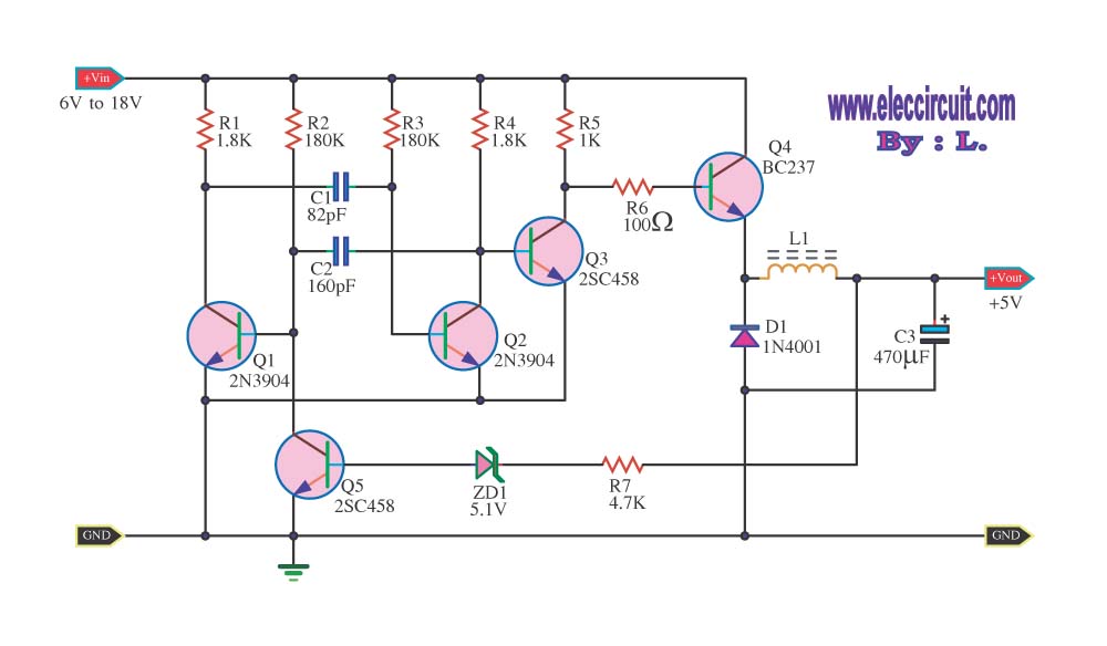
The step-down voltage converter, also known as a buck converter, is an essential circuit in power electronics, allowing for efficient voltage regulation and conversion. This type of converter operates by switching elements, typically a transistor, on and off rapidly to control the energy transfer to the output. The fundamental components include an inductor, a diode, a capacitor, and a control circuit.
In operation, when the switching element is turned on, current flows through the inductor, storing energy in its magnetic field. When the switch is turned off, the inductor releases the stored energy to the output load through the diode. The output voltage is regulated by adjusting the duty cycle of the switching signal, which is the ratio of the on-time to the total time of the switching cycle.
The design of the circuit must consider several factors, including the input voltage range, the desired output voltage, and the load current requirements. Additionally, the selection of the inductor and capacitor values is critical for ensuring stability and minimizing ripple voltage at the output.
The efficiency of the buck converter is typically high, often exceeding 90%, making it suitable for battery-powered applications where power conservation is essential. Proper thermal management and component selection are crucial to maintain performance and reliability in various operating conditions.
Overall, the step-down voltage converter circuit is a versatile solution for providing regulated DC voltage outputs in a wide range of electronic applications, from consumer electronics to industrial power supplies.The circuit decreases the size voltage or Stepdown Voltage converter circuit be dc regulated circuit model switching converter. The that make voltage output.. 🔗 External reference
Related Circuits
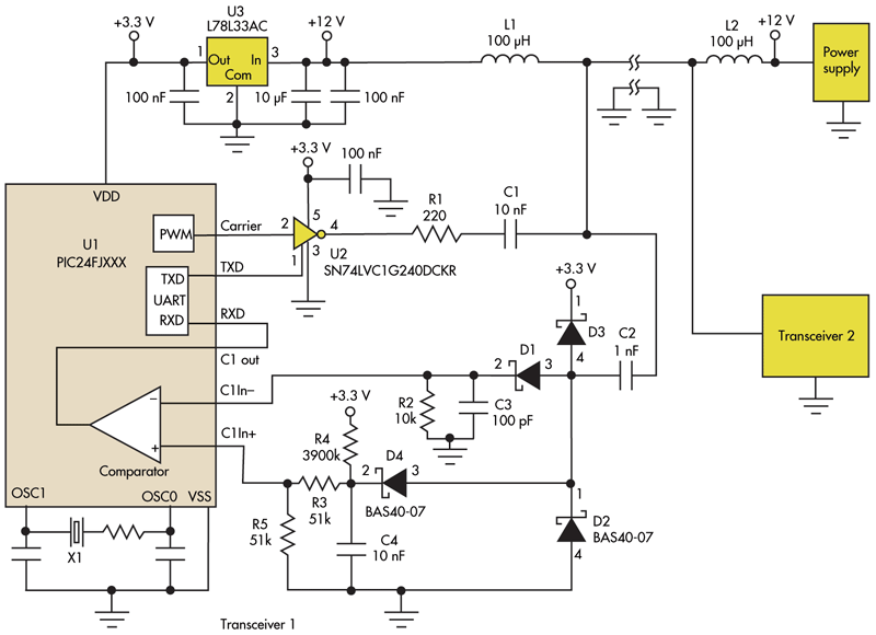
This circuit addresses the challenge of transmitting data over a cable that lacks available conductors. The data is modulated using On-Off Keying (OOK) and superimposed on a high-frequency carrier, allowing it to be transmitted over a low-voltage power supply...
Voltage regulator ICs with 3 pins, from the LM7805 and LM7812 series, are excellent for use in voltage regulator circuits. If higher currents are required, up to... Voltage regulator integrated circuits (ICs), specifically from the LM7805 and LM7812 series, serve...
This single transistor audio mixer is utilized in an amplifier circuit design featuring a base-driven transistor, where the emitter is current-controlled. The majority of the driving current flows through the collector. This audio mixer circuit employs a single transistor to...
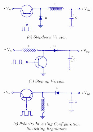
Switching voltage regulators include step-up, step-down, and polarity-inverting configurations, along with their working principles and circuit diagrams. Switching voltage regulators are essential components in modern electronic circuits, providing efficient voltage conversion. These regulators can be categorized into three main types:...
Anti-log or exponential generation involves rearranging logarithmic circuitry. The circuit diagram below illustrates the relevant circuitry. Anti-logarithmic or exponential circuits are essential in various applications, particularly in signal processing and analog computing. These circuits typically utilize operational amplifiers (op-amps) configured...
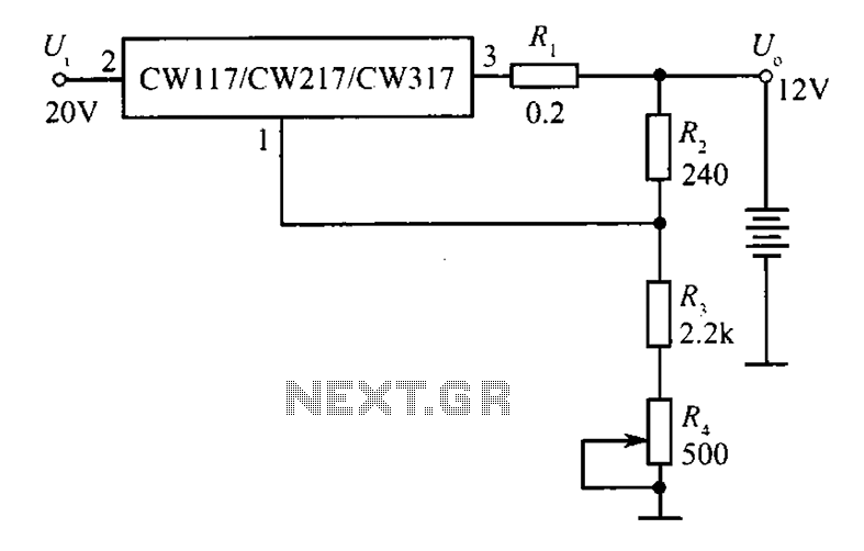
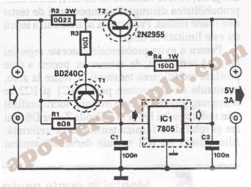
A 12V constant voltage charger is depicted. The power supply circuit shares the same basic design. The resistor R1, valued at 0.2 ohms, serves a limiting function, effectively increasing the internal resistance of the charger, which in turn reduces...