
Servicing old radios
In the process of reviving an old radio, a systematic approach is essential. Begin by inspecting the radio for physical damage or signs of wear, particularly around the power supply and output stages. After ensuring the radio is safe to power on, utilize the step-down transformer or Variac to gradually apply voltage, monitoring the current draw to prevent damage. The filter capacitors should be reformed carefully, as they can dry out and fail over time. This process involves applying a lower voltage and gradually increasing it while monitoring the voltage across the capacitors.
When measuring voltages within the radio, the use of a VTVM is recommended due to its high input impedance, which minimizes the loading effect on the circuit. For any high-voltage measurements, ensure that the multimeter is rated appropriately to prevent damage. When checking for leaky capacitors, utilize the voltmeter to measure across the capacitor while the circuit is powered, observing any unexpected voltage drops that may indicate leakage.
Finally, it is advisable to document any findings, repairs, or adjustments made during the servicing process to maintain a record of the radio's condition and history. This information can be invaluable for future maintenance or repairs. By following these guidelines, an old radio can be successfully revived, ensuring it continues to provide enjoyable audio for years to come.A radio that was stored for years on a dusty shelf must be awakened gently to return to its reliable operation and provide us with warm and pleasant sounds for years to come. Here are few generic notes on how a radio can be easily returned to life. Of course, more details can be found looking at each specific model. In addition to common tools, as screwdrivers, pliers, soldering iron and some brushes, we need few basic instruments. Some of the types, commonly in use in the past, are no longer manufactured. Some of the instruments still in production today can be more or less unsuitable for vacuum tube sets, where voltages could well be in the order of several hundreds volts. Anyway in many cases, old instruments still operating can be easily find at reasonable prices. Here an overview of instruments usually found in old service shops and their usefulness. A step-down transformer, a Variac or even an incandescent lamp, to reduce the mains voltage during the early power-on, is the most useful tool.
The step-down transformer is to be preferred when servicing radio sets with chassis directly connected to the AC mains. When a transformer is used, a 2 to 1 voltage ratio can be selected. We will start at half voltage and switch to the full voltage after the reforming of filter capacitors.
A soft start-up procedure is advisable even for radios already serviced in the past, if left inoperative for several months or years. Most of the digital multimeters, today available, have high input impedance, in the order of 10 Megaohms.
and are suitable to measure voltage and resistance inside our radio. Unfortunately the voltage range of modern multimeters is limited to few hundreds volts, unsuitable for some old electronic sets. I burned some digital multimeters, attempting to calibrate the HV supply in old Tektronix oscilloscopes.
For this reason, I prefer old fashioned moving coil multimeters but, in this case, an additional high input impedance VTVM is required for accurate measurements on grid circuits. Here are a couple of Avometer 8 and two of the most known VTVMs, the RCA Senior VoltOhmist WV-98C and the HP 410B.
Note that the Avometer on the left, a model 8 MK IV, has separate inputs for AC/DC ranges up to 2500 volts, useful to service some old lab instruments. HV inputs are no longer available on newer releases of the same model. I love Avometers because of their smooth taut-band movement, their performances, stable through the years, their effective protections against overloads and their incredible ruggedness, that make them indestructible.
In contrast to common believe, the insulation meter is not essential to find leaky coupling capacitors. DC leakage currents in a capacitor are always present to some extent, when a DC voltage is applied to its armatures.
It is important to evaluate how these currents affect the normal operation of involved circuits. The insulation meter returns at a given test voltage a resistance value, which can be represented in parallel to the capacitor itself, to calculate the DC shift of involved nodes. But the actual shift can be directly measured with a voltmeter, provided that its impedance is high enough to prevent appreciable influence on the circuit under test.
A VTVM, with its typical 10 Mohms input impedance, will just add a predictable 10% error, when measuring the voltage across a 1 Mohm grid resistor, and even less for lower resistance values. An insulation meter can give unpredictable errors, if the test is run at any voltage higher or lower than the actual operating one.
Rather the insulation meter it is useful to locate leakage paths that could impair operation or safety of the set being serviced. It is not uncommon to find leakage paths, as burned pa 🔗 External reference
Related Circuits

This area is primarily characterized by commercial information resellers. A notable exception is Nostalgia Air, which maintains an expanding database of radio schematics. Some links provided here direct to Nostalgia Air's database; however, if the desired information is not...
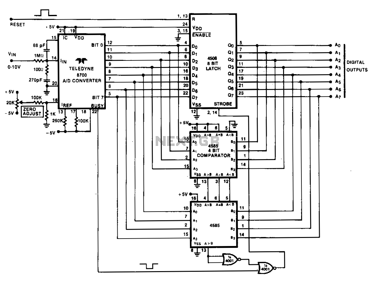
Analog peak detection is achieved by repeatedly measuring the input signal with an A/D converter and comparing the current reading with the previous reading. If the current reading is larger than the previous one, the current reading is stored...
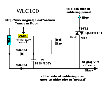
The following circuit illustrates the Weller WLC100 Electronic Soldering Station Circuit Diagram. This circuit utilizes the Q4012LPH Transistor. Features include safety measures, temperature control, and functionality as a soldering station that performs effectively for various applications. It is a...
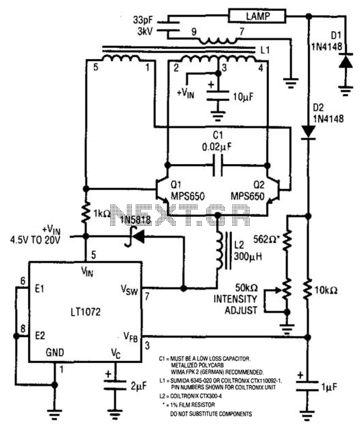
For backlit LCD displays, this supply will drive a lamp. The LT1072 drives Q1 and Q2, while a sine wave appears across C1. L1 is a transformer that steps up this voltage to approximately 1400 V. D1 and D2...
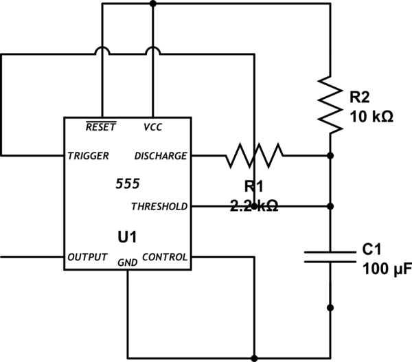
Bold lines indicate soldered connections, while arrows represent wire-based connections. Red indicates V_cc, black represents ground, blue signifies intermediate connections, and gold denotes the primary output. Pins 1 and 5 are connected to ground. It is noted that pin...
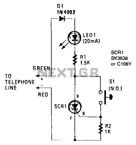
The on-hook (no load) voltage across the red-green wires will be 48 V or slightly less when all telephones are on-hook (disconnected). When any telephone goes off-hook, the load current flowing in the telephone causes the voltage to fall...
Warning: include(partials/cookie-banner.php): Failed to open stream: Permission denied in /var/www/html/nextgr/view-circuit.php on line 713
Warning: include(): Failed opening 'partials/cookie-banner.php' for inclusion (include_path='.:/usr/share/php') in /var/www/html/nextgr/view-circuit.php on line 713