
pcb design Need second set of eyes on 555 50% duty cycle soldered protoboard
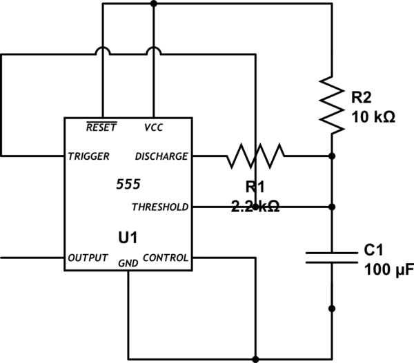
The circuit in question employs a 555 timer in a standard configuration, likely in either astable or monostable mode, based on the connections described. The use of bold lines for soldered connections and arrows for wire connections suggests a combination of permanent and temporary linkages, which is common in prototyping environments. The color coding system employed provides clarity in identifying the power supply (V_cc), ground connections, and signal paths.
It is critical to ensure that all connections are correctly made according to the specifications in the 555 timer datasheet, as errors in pin assignments can lead to circuit malfunction. The mention of verifying the resistors and capacitors indicates a systematic approach to troubleshooting. It is advisable to utilize a multimeter to check for continuity across the circuit, ensuring that all connections are secure and functioning as intended. Additionally, measuring the voltage at various points in the circuit can help identify where the signal is lost or if the voltage levels are not as expected.
For future troubleshooting, several tests can be conducted. First, a visual inspection of the circuit for any obvious soldering errors or loose connections can be beneficial. Second, using an oscilloscope to observe the output waveform can provide insight into the timing and behavior of the 555 timer, allowing for adjustments to be made based on the observed signal. Lastly, creating a checklist based on the datasheet specifications can help ensure that all components are correctly placed and functioning, minimizing the potential for errors in future designs.Bold lines are soldered connections, arrows are wire based connections. Red for V_cc, Black for ground, blue for intermediate connection and gold for primary output. Pins 1, 5 are connected to ground (I recognize that 5 should go to a capacitor to ground, but have omitted it here as it worked without it on the breadboard and space was limited) My first thought was that I damaged something during the soldering process, so I went through and verified that the resistors and capacitor were functioning. The 555 sits in a socket, and each of the socket connections is going through. So the big question is, what did I screw up in translating from the datasheet to this design And, in general, what tests can I conduct myself to identify how to solve "why isn`t my protoboard working" kind of problems in the future 🔗 External reference
Related Circuits
555 low power timing circuit diagram. The diagram is from the technical information of Chinaicmart. For more detailed information about the circuit diagram. The 555 timer IC is widely utilized in various applications due to its versatility and ease of...
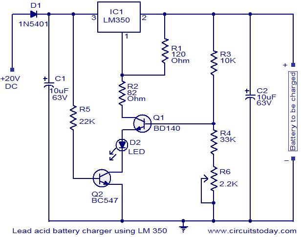
This circuit utilizes the IC LM350 for charging 12V lead-acid batteries, providing a constant voltage source with a negative temperature coefficient. The transistor Q1 (BD140) functions as a temperature sensor, while transistor Q2 prevents the battery from discharging through...
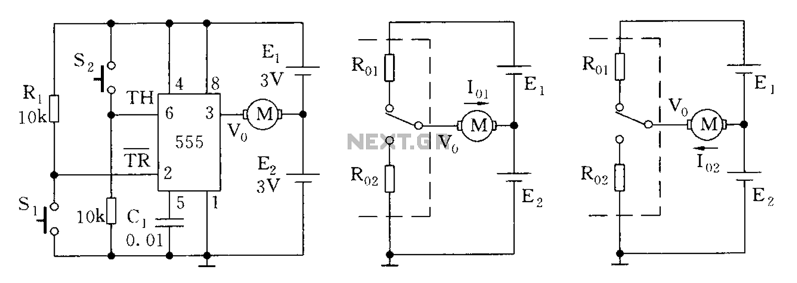
The 555 timer in bistable mode has fewer applications compared to its stable and monostable modes. Bistable mode refers to the circuit configuration based on the R-S (Reset-Set) trigger mode. An example of this is a micro-motor reversing control...
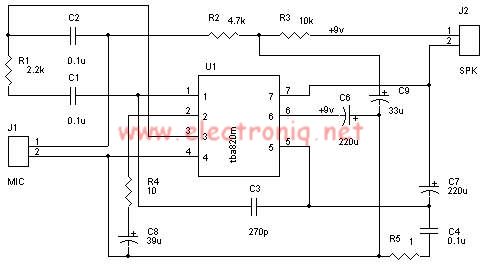
A very simple audio amplifier circuit can be designed using the TBA820M audio amplifier integrated circuit with just a few electronic components. This audio amplifier project features a high gain that allows for the detection of sounds underwater. The...
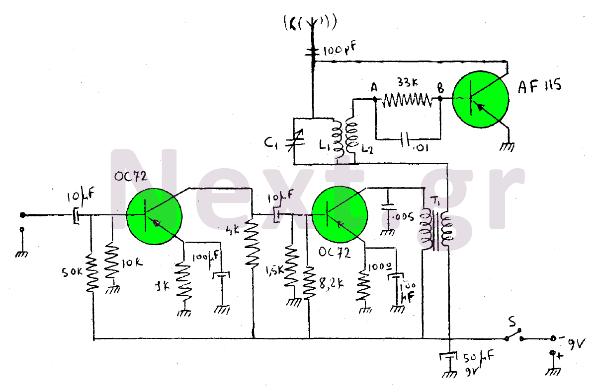
This device is a transmitter operating on medium-wave and short-wave frequencies, utilizing three transistors. The AF115 transistor serves as the oscillator within the circuit. The low-frequency amplifier, consisting of two OC72 transistors, functions as the modulator that generates the...
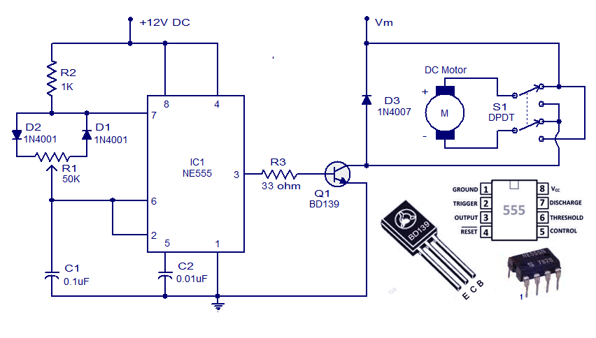
This weblog discusses electronic circuit schematics, PCB design, DIY kits, and electronic project diagrams. A simple DC motor controller circuit utilizing the NE555 timer is presented. Several DC motor speed control circuits are explored, with this being the first...
Warning: include(partials/cookie-banner.php): Failed to open stream: Permission denied in /var/www/html/nextgr/view-circuit.php on line 713
Warning: include(): Failed opening 'partials/cookie-banner.php' for inclusion (include_path='.:/usr/share/php') in /var/www/html/nextgr/view-circuit.php on line 713