
Servicing Radio And Sound Equipment
The architecture of a typical vacuum tube transmitter circuit is characterized by its various components working in harmony to achieve efficient RF signal transmission. The tank circuit, consisting of inductors and capacitors, plays a critical role in tuning the transmitter to the desired frequency. The blocking capacitors serve to isolate the RF signal from other DC or low-frequency signals, ensuring that the transmitter operates effectively without interference.
In the series feed configuration, the DC voltages are fed directly through the tuned circuit, which can enhance the quality of oscillation and stability of the RF output. Conversely, the parallel feed arrangement allows for greater flexibility in circuit design and can be advantageous in certain applications where isolation from the tuned circuit is necessary.
The importance of the center-tap configuration in filament-type tubes cannot be overstated, as it directly impacts the noise performance of the transmitter. Proper grounding and return paths are essential to minimize hum and ensure clean signal amplification.
The excitation voltage applied to the grid is a key parameter that influences the overall performance of the transmitter. It should be carefully controlled to optimize the output power while avoiding distortion. The distinction between power input and output is also critical for evaluating the efficiency of the transmitter; understanding these parameters aids in the design of more effective circuits.
Antenna design considerations are integral to the overall transmitter design, as the impedance matching between the output circuit and the antenna is vital for maximizing radiated power. The use of loading networks allows for dynamic adjustments to the antenna's effective length, accommodating various transmission conditions.
Intermediate amplifiers are essential for boosting the signal strength before it reaches the final power amplifier stage. These amplifiers must be designed to handle the specific frequency range generated by the oscillator while maintaining linearity and minimizing distortion.
Buffer amplifiers serve a critical function in isolating the oscillator from the subsequent stages, ensuring that the oscillator's performance is not compromised by load variations. This isolation is particularly important in environments where the transmitter may experience fluctuating power demands.
The power amplifier stage is the final link in the transmission chain, responsible for delivering the amplified RF signal to the antenna. The design of the output circuit must ensure that the impedance mismatch between the amplifier and the antenna is effectively managed, often through the use of matching networks that incorporate both inductive and capacitive elements.
In summary, the design of vacuum tube transmitter circuits involves a complex interplay of various components, each serving a specific purpose to achieve optimal performance in RF signal transmission. Understanding these interactions is key to developing effective and efficient transmitter designs.The tuned circuits of capacity and inductance used in vacuum tube transmitter circuits are frequently called "tank" circuits, because from one viewpoint they act as tanks or reservoirs of RF energy. Blocking Capacitors. -Blocking capacitors are used to provide a high impedance path for DC or low-frequency AC, and so prevent the flow of such currents
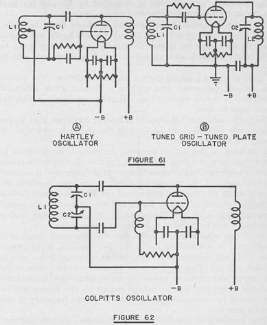
without appreciably affecting the flow of RF. Series and Parallel Feed. -The DC grid and plate voltages required for tube operation may be fed through the coil of the tuned circuit, or may be fed through a choke in parallel with the tuned circuit. In the first case the voltage feed is called series feed, in the second, it is called parallel feed. The connections are shown in Figure 59. Filament Center-Tap. -When filament type tubes are heated by AC, the grid and plate returns must be made to the electrical center, or center-tap, of the filament circuit in order to avoid hum.
Excitation. -In transmitters, the AC signal voltage applied to the grid of a tube is called the excitation, or the exciting or driving voltage. Exciting or driving power is the power required to develop the exciting voltage across the grid circuit.
Oscillators supply their own excitation, but amplifiers must be driven by voltage from an oscillator or from another amplifier. Power Input. -Unless otherwise specified, the term power input applies to the DC power consumed in the plate circuit.
It is the product of the DC plate voltage and current. Power Output. -It is important to distinguish between the tube power output and the circuit power output. The tube output does not take into account the tank and coupling circuit losses. Antenna Feeding. -Distances along an antenna are usually expressed in terms of electrical wave length. Every half wave length there will be a point of high RF voltage. There will be a high current point half way between any two high voltage points, that is at the quarter-wave points. A voltage fed antenna is one which is excited at one of the high voltage points, that is at a point of high impedance.
A current fed antenna is one that is fed at a point where the current is high and the -voltage low, or a point of low impedance. Transmitters often have loading networks built into the output circuit which may be switched in and out to change the effective electrical length of the antenna.
Intermediate Amplifiers. -These amplifiers take the RF generated by the oscillator and increase the signal to sufficient strength to drive the power amplifier output stage. Intermediate amplifiers may be designed so that their output frequency is higher than the oscillator Buffer Amplifiers.
-Oscillator circuits will be most stable as frequency generators when they are not required to deliver appreciable power, especially when the power demand fluctuates. Consequently, a buffer amplifier is frequently used as the first stage after the oscillator. This buffer needs only a small driving voltage from the oscillator and may transfer the signal voltage to the next amplifier without amplifying it.
Such a circuit serves to isolate the oscillator from changing conditions in the later stages of the transmitter and hence the name buffer. Power Amplifier. -This final amplifier is excited by the intermediate amplifiers and increases the signal power to the desired output value before delivering it to the antenna circuits.
Output Circuits. -The plate circuit load of the power amplifier must usually be a fairly high impedance if the amplifier is to operate effectively. An antenna is usually a rather low impedance circuit. The transmitter output circuits must be designed to couple, or match, these two different impedances so that the maximum energy practicable will be usefully fed into the antenna.
Various arrangements of inductance and capacity are used in the coupling networks. Harmonics or Harmonic Series. -Although a crystal or a resonant 🔗 External reference
Related Circuits
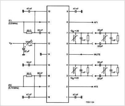
The TDA3567 is a monolithic integrated decoder designed for the NTSC color television standards. It incorporates all the necessary functions for the demodulation of NTSC signals. Additionally, it features a luminance amplifier and an RGB matrix amplifier. These amplifiers...
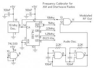
The following circuit illustrates an AM/Shortwave Radio Frequency Calibrator Circuit Diagram. This circuit is based on the 74LS93 IC. Features: The .. The AM/Shortwave Radio Frequency Calibrator Circuit utilizes the 74LS93 integrated circuit, which is a 4-bit binary counter. This...
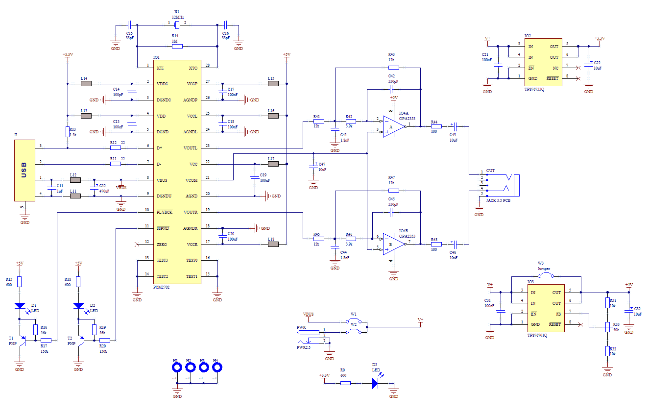
If you use great IC PCM2702 from BURR BROWN / Texas Instruments you can create a fully functional USB sound card. This sound card can be powered from USB port and has one stereo output. You don’t need to...
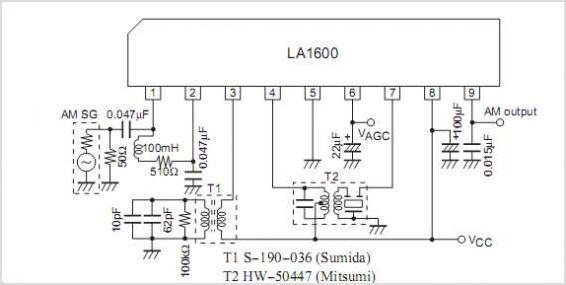
The LA2010 is an integrated circuit designed for detecting interprogram spaces, allowing for the identification of the starting point of a program that immediately precedes or follows a musical program recorded on tape. It is manufactured by Sanyo Semiconductor...
This circuit is designed to trigger on a 1 kHz tone. To change this frequency, refer to the table below, then change the resistor and capacitor values accordingly. More: all resistors are 5 or 10 percent tolerance, 1/4-watt; all...
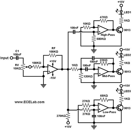
The simple circuit for converting an audio signal. The circuit basically consists of a buffer/amplifier stage and three filter circuits. The audio signal conversion circuit is designed to process audio signals efficiently while maintaining signal integrity. The circuit architecture includes...