
sound detector tone decoder
The described circuit functions as a frequency-sensitive triggering mechanism, specifically designed to activate in response to a 1 kHz audio tone. The fundamental operation likely involves a combination of resistors and capacitors configured in an RC timing circuit, which determines the frequency of oscillation.
To modify the frequency of the circuit, it is essential to adjust the values of the resistors and capacitors according to a predefined table, which presumably outlines the necessary component values for various target frequencies. The choice of resistors with a tolerance of 5% or 10% and a power rating of 1/4 watt ensures that the circuit maintains a reliable performance under typical operating conditions. Similarly, the capacitors are specified with a tolerance of 10% and a voltage rating of at least 35 volts, which provides adequate headroom for voltage fluctuations and ensures the longevity of the components.
The circuit may include additional features such as a comparator or a microcontroller to process the incoming tone and provide a digital output or trigger an external device. This could be beneficial in applications where precise tone detection is required, such as in alarm systems, audio processing, or communication devices.
For practical implementation, it is advisable to use a breadboard for initial testing, allowing for easy adjustments of component values to achieve the desired frequency response. Once the circuit is finalized, a PCB design can be created to ensure a compact and robust deployment in a final product. Proper layout considerations should be taken to minimize noise and interference, particularly in environments with other electronic devices.This circuit is designed to trigger on a 1 khz tone. to change this frequency - refer to the table below, then change the resistor and capacitor values accordingly. all resistors are 5 or 10 percent tolerance, 1/4-watt all capacitors are 10 percent tolerance, rated 35 volts or higher 🔗 External reference
Related Circuits
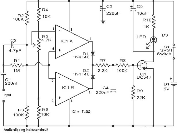
Clipping is a significant issue that leads to distortion in amplifiers. It results in the amplitude level of a waveform dropping abruptly before it reaches its intended limit. This document presents a straightforward circuit designed to detect clipping in...
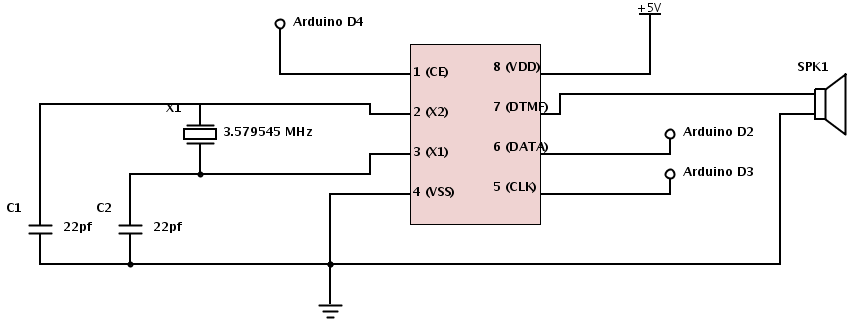
The project involves teaching an Arduino to generate DTMF (Dual-Tone Multi-Frequency) tones using the HT9000A DTMF chip. These tones are the familiar "touch tones" used in telephone systems. The output volume from the chip is low, suggesting the need...
The Bachmann Big Hauler locomotive has significantly improved in appearance, reliability, and noise level over the past few years. However, the sound system remains basic, providing a poor imitation of exhaust sounds in the form of a chuff synchronized...
This circuit utilizes small switching transistors, with a maximum motor drive current limited to approximately 250 mA at 5V. Testing has been conducted across a voltage range from 3V to 21V, and with certain component modifications, it may be...
Capacitor discharge firing boxes are suitable for specific types of electric match ignition but not for others. Experimenting with this technology can be enjoyable and educational; however, the expense of a commercial capacitor discharge (CD) firing box can be...
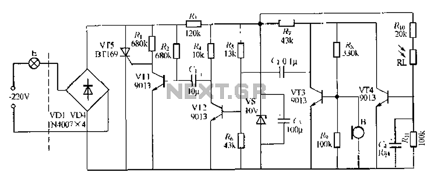
This circuit describes a sound and light control delay system for a walkway stairs light switch. It involves various components including 220V AC electric bulbs, diodes (VD1-VD4), and resistors. The circuit utilizes a rectifier regulator to stabilize the voltage...