
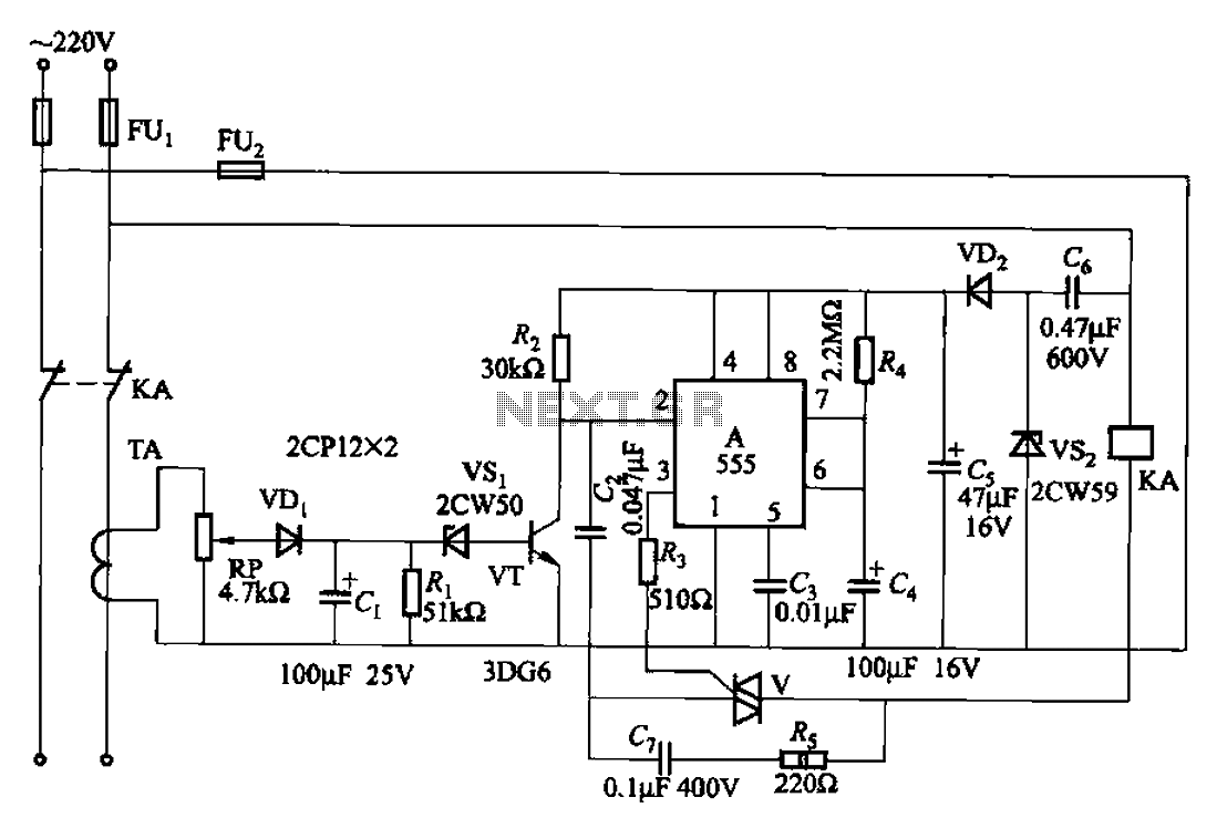
Servo controller with 555
In this circuit, the NE555 timer is configured as an astable multivibrator, producing a pulse-width modulation signal suitable for controlling RC servo motors. The circuit accepts a control voltage in the range of 0-10V, typically sourced from an analog light control desk, and outputs a pulse width that varies between 1 ms and 2 ms, with a frequency of approximately 80 Hz.
The timing capacitor, which is a 220 nF capacitor, is charged through a 33 kohm resistor. The charging time is influenced by the control voltage applied to pin 5 of the NE555, which is regulated to approximately 1.6V. As the control voltage increases, the charging current through the resistor also increases, resulting in a quicker charge time. For instance, at a control voltage of 10V, the capacitor charges in about 1 ms.
Once the capacitor reaches its maximum charge, the NE555 timer begins to discharge it through a 100 kohm resistor. The discharge continues until the voltage across the capacitor drops to half of the control voltage. In this configuration, the discharge time is approximately 11 ms, determined by the resistor between pins 2 and 7 of the NE555.
The circuit includes a 470 ohm trimmer that is used to fine-tune the control voltage at pin 5 of the NE555 to ensure it remains around 1.6V. This adjustment is crucial for calibrating the center position and control range of the connected RC servo. The circuit also incorporates a 1N4148 diode, which helps in protecting the circuit from potential back EMF generated by the servo motor.
The complete parts list for the circuit includes:
- 2 x 100 kohm resistors
- 1 x 47 kohm resistor
- 1 x 33 kohm resistor
- 1 x 470 ohm trimmer
- 1 x 1N4148 diode
- 1 x 220 nF capacitor
- 1 x 100 nF capacitor
- 1 x NE555 timer IC
This design effectively converts a 0-10V control signal into a suitable pulse for RC servo motors, with an estimated component cost of less than 10 US dollars, making it a cost-effective solution for various applications requiring precise motor control.This circuit takes standard 0-10V control voltage (for example from analogue light controlling desk) and outputs a standard 1-2 ms RC servo motors control pulse. Power supply: 4-5V DC (same as for RC servo), consumes 15 mA of current. Control voltage range: 0-10V. Control input impedance: > 30 kohm. Output control signal suitable for RC servo motors: 1-2 ms pulse with and pulse repeat rate is around 80 Hz.
Estimated component cost: less than 10 US dollars. Circuit performance: Protototypes have worked very well. Circuit is based on NE555 timer chip In this circuit NE555 is configured as astable multivibrator. The main timing capacitor (220 nF) is always changed to the voltage level which is determined by the voltage on NE555 pin 5 (in this circuit that voltage is aroun 1.6V). When the timing capacitor is charged only with current coming through 33 kohm resistor, the charging takes around 2 milliseconds.
When control voltage is appied to control input, the charging current increased when conrol voltage increases. When th econtrol voltage is 10V, the charging takes around 1 millisecond. When the capacitor is fully charged, NE555 starts to discharge the capacitor through 100 kohm resistor.
The discharging continues until the voltage has reached the half of the control voltage (1.6V/2=0.8V). The discharge time is determined by the resistor between NE55 pins 2 and 7. The 100 kohm resistor in this circuit makes this time to be around 11 milliseconds. When the capacitor is discharged, the circuit start charging it again. The 470 ohm trimmer in the circuit should be adjusted so that the pin 5 of NE555 IC receives a control voltage of around 1.6V.
When a RC servo is connected to the circuit, you can slightly adjust the trimmer to adjust the center position and control range. Parts: 100 kohm resistor 2 47 kohm resistor 1 33 kohm resistor 1 470 ohm trimmer 1 1N4148 diode 1 220 nF capacitor 1 100 nF capacitor 1 NE555 timer IC 1
🔗 External reference
Related Circuits
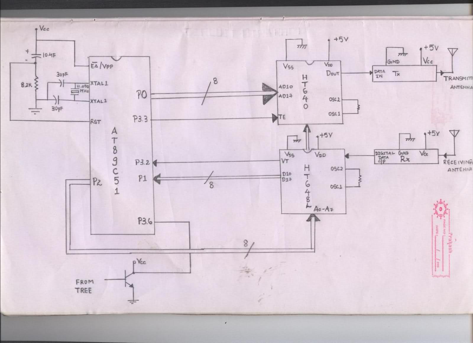
The issue arises when connecting the 8051 microcontroller to the HT640 encoder; the data sent is not received at the receiver. However, when the connections to the 8051 are removed, the transmission functions perfectly. This indicates that manual RF...
Figure 15-22 illustrates a doorbell system that consists of a monostable timing circuit, a password switch, a NAND gate circuit, and a sound output circuit. The operation of the circuit is designed such that when the password switch is...
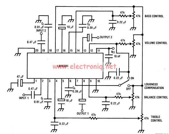
This volume controller equalizer electronic project is designed using the LM1036 DC tone volume controller, featuring a volume and balance circuit for stereo applications. The four control inputs of the LM1036 volume controller enable the control of bass, treble,...
The controller uses one or more ordinary silicon diodes as a sensor, and uses a cheap opamp as the amplifier. I designed this circuit to use 12V computer fans, as these are now very easy to get cheaply. These...
The 555 limit circuit, which is an integrated electrical circuit, is designed to manage large electrical loads. It automatically disconnects power when the load exceeds a predetermined threshold. Once the load is reduced below this threshold, power is restored...
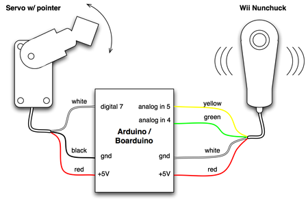
The small footprint of the Boarduino prompted an exploration into how compact a device could be created in one hour using various complex components. The combination of a Boarduino, a Wii Nunchuck, and a hobby servo motor was chosen...