
Motor Fan heat controller
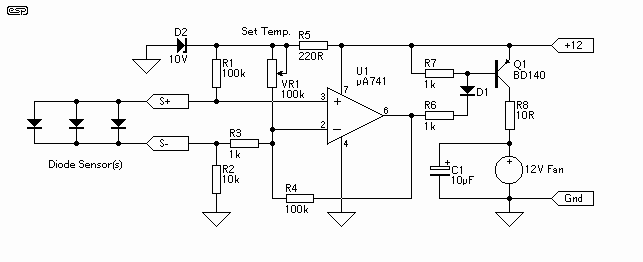
The described circuit utilizes silicon diodes as temperature sensors, which exhibit a predictable forward voltage drop that varies with temperature. The operational amplifier (op-amp) serves as a comparator, amplifying the small voltage signal produced by the diodes to a level sufficient to control a power transistor. The circuit is powered by a 12V supply, suitable for driving standard computer fans that typically consume around 200mA.
The BD140 transistor is employed as a switch, capable of handling up to 1A of current, making it suitable for controlling the fan operation. Its characteristics allow for effective switching with minimal heat generation, given the low power requirements of the fan. The circuit design enables the use of various substitute transistors, provided they meet the necessary current and voltage specifications.
A variable resistor, designated as VR1, is incorporated into the circuit to set the desired temperature threshold. The operational amplifier is initially adjusted to stabilize at the normal operating temperature. As the temperature rises above this threshold, the op-amp output activates the transistor, which in turn powers the fan, providing cooling. The fan will continue to operate until the temperature drops back to the set point, at which point the circuit will deactivate the fan.
This feedback mechanism ensures that the fan operates only when necessary, enhancing energy efficiency and prolonging the lifespan of the components. The simplicity of the design, combined with the availability of parts, makes this circuit an effective solution for temperature control in various applications.The controller uses one or more ordinary silicon diodes as a sensor, and uses a cheap opamp as the amplifier. I designed this circuit to use 12V computer fans, as these are now very easy to get cheaply. These fans typically draw about 200mA when running, so a small power transistor will be fine as the switch.
I used a BD140 (1A, 6.5W), but almost anything you have to hand will work just as well. The temperature is set with VR1. Operate the amp until the normal temperature is reached, then adjust VR1 until the fan starts. Then back off very slowly until the fan stops again. Any increase over the normal temperature will start the fan, and promptly 🔗 External reference
Related Circuits
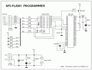
This ISP programmer can be utilized for in-system programming or as a standalone SPI programmer for Atmel ISP programmable devices. The programming interface is compatible with STK200 ISP programmer hardware, allowing users of STK200 to employ the software, which...
This project has been set aside for several years. It was initially intended for programming old 8051 microcontrollers, which have since become obsolete. The project was recently revisited due to the need for a programmer for the Atmel Xmega...

This is a speed motor controller circuit for a 12V DC motor. The speed of rotation of the spindle motor can be adjusted from 5 to 60 cycles per minute. The speed motor controller circuit for a 12V DC motor...
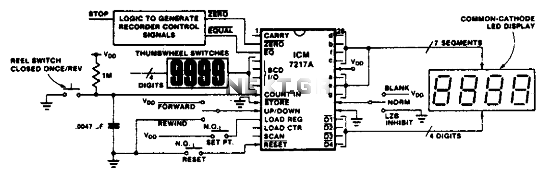
This circuit illustrates various applications of up/down counting for monitoring dimensional position. In the tape recorder application, the LOAD REGISTER, EQUAL, and ZERO outputs are utilized to control the recorder. To ensure the recorder stops at a specific point...
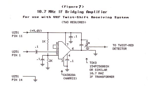
The material in this section demonstrates the construction of the Twist-Shift system for VHF utilizing commonly available surplus land mobile VHF transceivers that have been modified to operate on the 2-meter ham band. The radios employed in this project...
The BTS412B functions as two high-side power MOSFET switches, while the BU271L components rated for 50V serve as the low-side switches. Together, these elements can form a bi-directional H-bridge DC motor drive circuit, as depicted in Figure 11-1l. This...
Warning: include(partials/cookie-banner.php): Failed to open stream: Permission denied in /var/www/html/nextgr/view-circuit.php on line 713
Warning: include(): Failed opening 'partials/cookie-banner.php' for inclusion (include_path='.:/usr/share/php') in /var/www/html/nextgr/view-circuit.php on line 713