
Servo controlling circuit
- 2 x 100 kΩ resistors
- 1 x 47 kΩ resistor
- 1 x 33 kΩ resistor
- 1 x 470 Ω trimmer
- 1 x 1N4148 diode
- 1 x 220 nF capacitor
- 1 x 100 nF capacitor
- 1 x NE555 timer IC
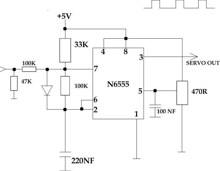
This circuit is designed to control an RC servo from a light control desk that provides a 0-10V control voltage output. The slider on the light control desk modulates the output voltage within this range. The circuit processes this control voltage and generates pulses that dictate the position of an RC servo motor, commonly used in radio-controlled cars, boats, and planes. A suitable +5V power source is required to operate this circuit.
To utilize the circuit, the RC servo is connected to the output, with the control input pin of the servo motor linked to the circuit output. The ground of the servo motor should be connected to the circuit ground, while the power input of the servo is connected to an appropriate power source, which can also be the same +5V used for the circuit. The pinouts on different servo motors may vary, but typically, black is ground, red is power, and the third wire is the control input.
An adjustable 0-10V control voltage source is also necessary. This can be achieved using a laboratory power supply, the aforementioned light control desk, or a 1 kΩ potentiometer connected to a 10V power source (ground to one end, +10V to the other end, with the control voltage taken from the center). The control voltage directly influences the position of the connected RC servo motor. A 0V input will position the servo at one extreme, while 10V will move it to the opposite end, and 5V will place it around the center position.
The 470 Ω trimmer in the circuit should be adjusted so that pin 5 of the NE555 IC receives a control voltage of approximately 1.6V. With the RC servo connected, slight adjustments to the trimmer can fine-tune the center position and control range of the servo. In this circuit, the NE555 is configured as an astable multivibrator. The primary timing capacitor (220 nF) is charged to a voltage determined by the voltage on pin 5 of the NE555 IC, which is around 1.6V in this setup.
The charging process of the timing capacitor occurs solely through the current flowing through the 33 kΩ resistor, taking approximately 2 milliseconds to charge. When the control voltage is applied to the control input, the charging current increases with the control voltage. At a control voltage of 10V, the charging time reduces to around 1 millisecond. Once the capacitor is fully charged, the NE555 begins discharging it through the 100 kΩ resistor. This discharge continues until the voltage drops to half of the control voltage (1.6V/2 = 0.8V). The discharge time is influenced by the resistor between pins 2 and 7 of the NE555. The 100 kΩ resistor in this circuit results in a discharge time of approximately 11 milliseconds.This circuit takes standard 0-10V control voltage (for example from analogue light controlling desk ) and outputs a standard 1-2 ms RC servo motors control pulse. Component How many 100 kohm resistor 2 47 kohm resistor 1 33 kohm resistor 1 470 ohm trimmer 1 1N4148 diode 1 220 nF capacitor 1 100 nF capacitor 1 NE555 timer IC 1 I designed this circ
uit to control an RC servo from a light control desk that gave 0-10V control voltage out. In the light controlling desk the slider on the light controlling desk control the output voltage in 0-10V range. This circuit takes this control voltage in and generates a pulses that control a RC servo motor position based on this (those small servo motors that are used to control different things ar radio controlled cars, boats, planes etc.
). You need a suitable +5V power source to run this circuit. To use the circuit you connect RC servo to the circuit output to a suitable RC servo. The output of the circuit goes to control input pin in servo motor, servo motor ground goes to circuit ground and servo power input goes to suitable power source (can be the same 5V as used to power this circuit). The pinouts used on differnet servo motors vary, but the wire colors are generally so that black is ground, read is power and the third wire is the control input.
In addition to this you need an adjustable 0-10V control voltage source. This can be a laboratory power supply, light controlling desk that give out 0-10V output, a 1 kohm potentiometer wired to 10V power source (wire ground to one end, +10V to other end take control voltage from the center). The control voltage will control the position of the RC servo motor connected to the output. When you change the voltage, the servo will move to the new position corresponding to the new control voltage value.
0V gets the servo to one extreme, and 10V to other end, and 5V puts the servo to around center position. That`s how the circuit works. The 470 ohm trimmer in the circuit should be adjusted so that the pin 5 of NE555 IC receives a control voltage of around 1.
6V. When a RC servo is connected to the circuit, you can slightly adjust the trimmer to adjust the center position and control range. In this circuit NE555 is configured as astable multivibrator. The main timing capacitor (220 nF) is always changed to the voltage level which is determined by the voltage on NE555 pin 5 (in this circuit that voltage is aroun 1.
6V). When the timing capacitor is charged only with current coming through 33 kohm resistor, the charging takes around 2 milliseconds. When control voltage is appied to control input, the charging current increased when conrol voltage increases.
When th econtrol voltage is 10V, the charging takes around 1 millisecond. When the capacitor is fully charged, NE555 starts to discharge the capacitor through 100 kohm resistor. The discharging continues until the voltage has reached the half of the control voltage (1. 6V/2=0. 8V). The discharge time is determined by the resistor between NE55 pins 2 and 7. The 100 kohm resistor in this circuit makes this time to be around 11 milliseconds. 🔗 External reference
Related Circuits
Modern acid batteries and lead plates are embodiments of simplicity in use. Unlike NiCd batteries, they must be recharged by connecting to a constant voltage source. Modern acid batteries, commonly referred to as lead-acid batteries, consist of lead plates submerged...
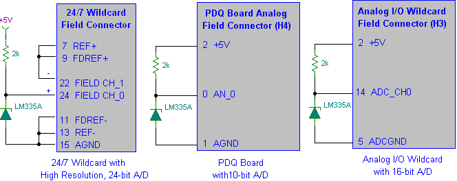
Interfacing the LM335A temperature sensor with A/D converters involves measuring temperature using the LM35 and LM335A sensors alongside the 9S12 HCS12 microcontroller. This process includes analyzing both calibrated and uncalibrated temperature errors of integrated circuit temperature sensors. The LM335A is...
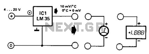
An effective temperature sensor circuit is designed to receive power from a 4-to-20 mA loop without impacting the loop current. The temperature sensor integrated circuit (IC) used is the AD590F, which operates with a supply voltage ranging from 4...
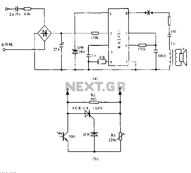
The circuit utilizes a standard telephone ringing circuit, KA2401, along with additional components to control lighting in response to a ringing signal. The light control circuit can be activated externally by AC when the ringing signal is received. The...
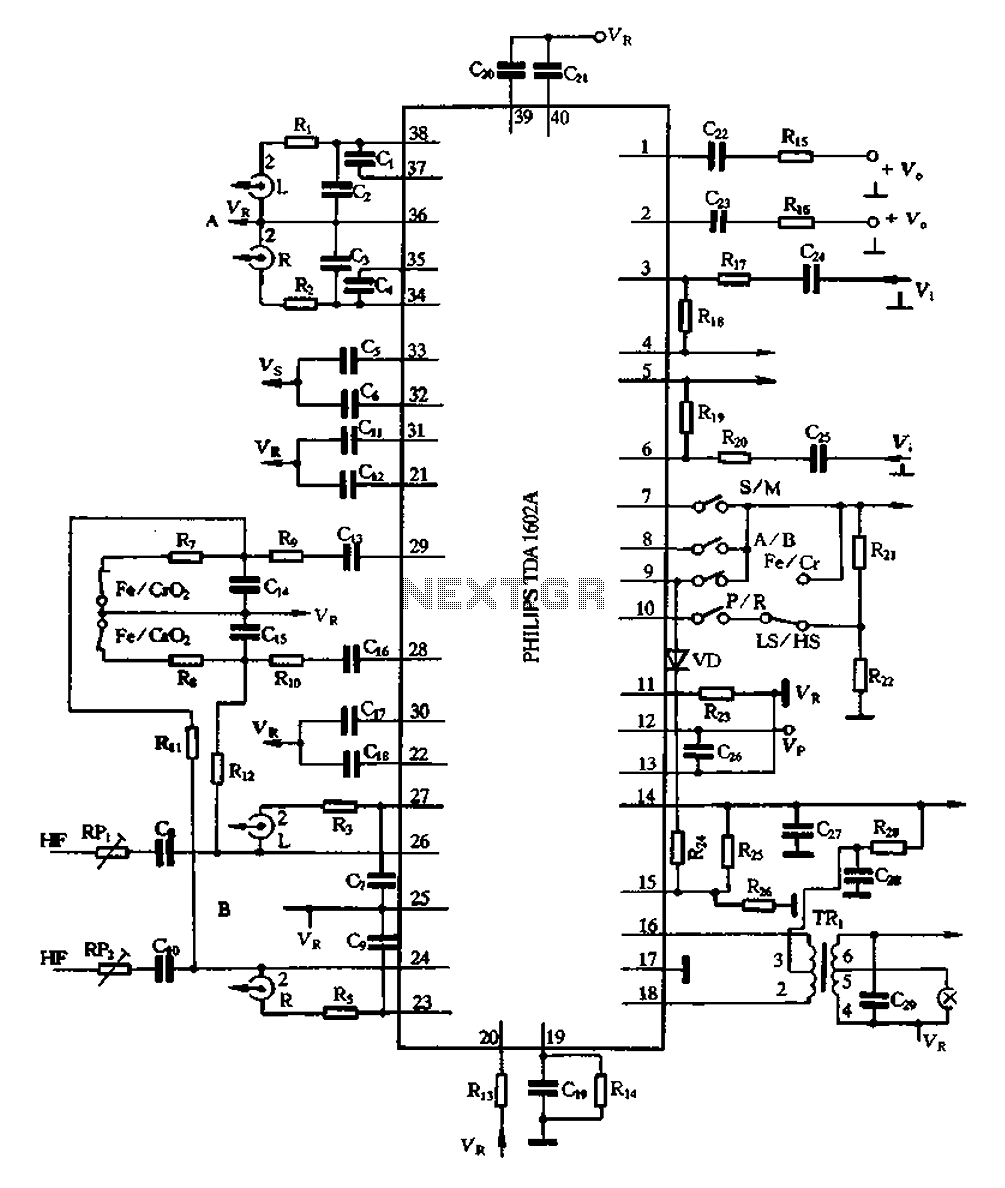
The A1602A is a 40-pin dual in-line package that functions as a playback preamplifier. It utilizes linear low-noise amplifiers with a voltage gain of 26.4 dB. Each channel has a separate discharge sound preamplifier, selected by an electronic switch...
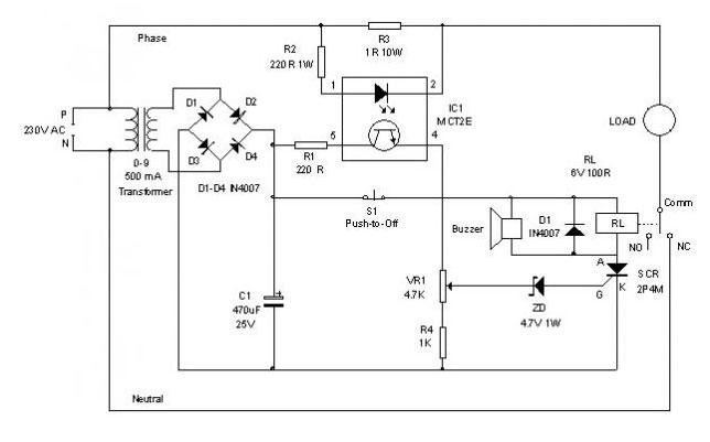
An electronic circuit breaker is designed to detect overload conditions and disconnect power when the load exceeds a predetermined threshold. This circuit is particularly suitable for safeguarding Uninterruptible Power Supply (UPS) devices, such as inverters. The electronic circuit breaker operates...
Warning: include(partials/cookie-banner.php): Failed to open stream: Permission denied in /var/www/html/nextgr/view-circuit.php on line 713
Warning: include(): Failed opening 'partials/cookie-banner.php' for inclusion (include_path='.:/usr/share/php') in /var/www/html/nextgr/view-circuit.php on line 713