
Servo Driver

Servo wire colors can vary significantly due to conflicting standards, although control signals remain consistent. The +V wire is always red and is typically positioned in the center of the 3-wire connector, except in KO and older Airtronics style servos where the -V wire occupies the center position. The -V wire is generally black (brown on JR, and blue on newer Airtronics style servos). The control signal wire is never centered in the connector and can be yellow, orange, white, blue, or black. For 4-wire (Kraft style) servos, the additional wire serves as a midpoint voltage "ground," which is intended to be precisely midway between +V and -V.
The circuit employs the LM555 timer IC, configured in astable mode to generate pulse-width modulation (PWM) signals suitable for controlling servo motors. The resistors R1 and R2, along with capacitors C1 and C2, determine the frequency and duty cycle of the output signal, which is critical for servo operation. The linear potentiometer (P1) allows for manual adjustment of the control signal, enabling precise positioning of the servo.
The diode (D1) protects the circuit from potential back EMF generated by the servo during operation. The circuit's design allows for versatility in applications, from simple testing to complex robotic implementations. Proper attention to the wiring standards for servos is essential to ensure compatibility and prevent damage during operation. Additionally, the circuit's ability to exceed standard pulse widths can be leveraged for applications requiring greater servo travel, but careful adjustments must be made to avoid unintended overtravel.This circuit can be used to check the operation of your servos, check for full travel, binding and "drag" or rubbing when the servos are installed in your model, or even be used as a control circuit in a robotics project. PARTS LIST: IC1 = LM555 Timer (or equiv. ) R1 = 18K (Brown-Gray-Orange; 183) C1 = 0. 033uF (33nF; 333) R2 = 680K (Blue-Gray-Yello w; 684) C2 = 0. 1uF (100nF; 104) D1 = 1N4148 or other small P1 = 50K Linear Potentiometer silicon signal diode The simple, inexpensive circuit above can vary the control pulses from about 0. 6 to 2. 4 mSec, and handle control signal currents up to 200 mA. (If your servo`s control input needs this much current, something is wrong!) This should be sufficient to achieve standard or greater control horn deflection with all servos.
At Vin = 4. 8 volts, positive pulse amplitude is about 4 volts at a frame rate of about 50 Hz (20 mSec). For more info on how servos work, see my Servo. txt file. Warning: this circuit can produce pulses which exceed the nominal limits of 1. 0 to 2. 0 mSec, which can cause servos to attempt to overtravel or behave strangely in the regions near the travel limits. A side effect of this is that servos will have MORE travel (or "throw") when using this ciruit than they will when using most R/C radio setups.
If you wish to change the travel provided by this circuit, decreasing R1 will shift both endpoints in one direction. Increasing R1 will shift both endpoints in the opposite direction. Adding a resistor between pin 7 of the 555 and +V will shift both endpoints in the same direction as increasing R1, but will also reduce the total travel - try 680K to start, reduce this to reduce travel further.
If you want a high degree of adjustability in the circuit, replace R1 with a 50K trim rheostat, and put a 1Meg trim rheostat in parallel with the end taps of P1. If your servos sometimes shudder and fail to track the potentiometer position properly (and you have the travel adjusted well within the servo`s mechanical and electrical limits), this may be caused by weak batteries or too high a frame rate.
If fresh batteries do not cure the problem, decrease the frame rate by increasing R2 to 750K or more. Servo wire colors: There are several conflicting standards for servo wiring, even though the control signals are the same.
The only constant is that the +V wire is always red. The +V wire is usually in the center position of the 3-wire connector, except on KO and older Airtronics style servos which have the -V wire in the center. The -V wire is usually black (brown on JR, and blue on newer Airtronics style servos. ) The control signal wire is never in the center of the connector, and it can be yellow, orange, white, blue or black.
If you happen to have 4-wire (Kraft style) servos, the 4th wire is a midpoint voltage "ground" which is supposed to be exactly halfway between +V and -V. 🔗 External reference
Related Circuits
This is an efficient flyback driver for modern cylindrical rectified television flybacks. Many sites do not provide circuits for driving these transformers; they simply state that they are ineffective. However, this circuit has been built and tested, focusing on...
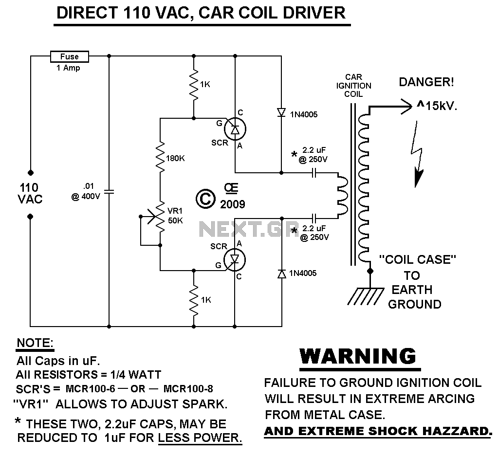
This Spark Can Be Very DANGEROUS, So BE CAREFUL. WARNING: FAILURE TO DO SO: WILL CAUSE THE CASE OF THE COIL TO ALSO BE ELECTRIFIED! NOTE You MUST have a LOAD on the High Voltage Output. With NO LOAD,...
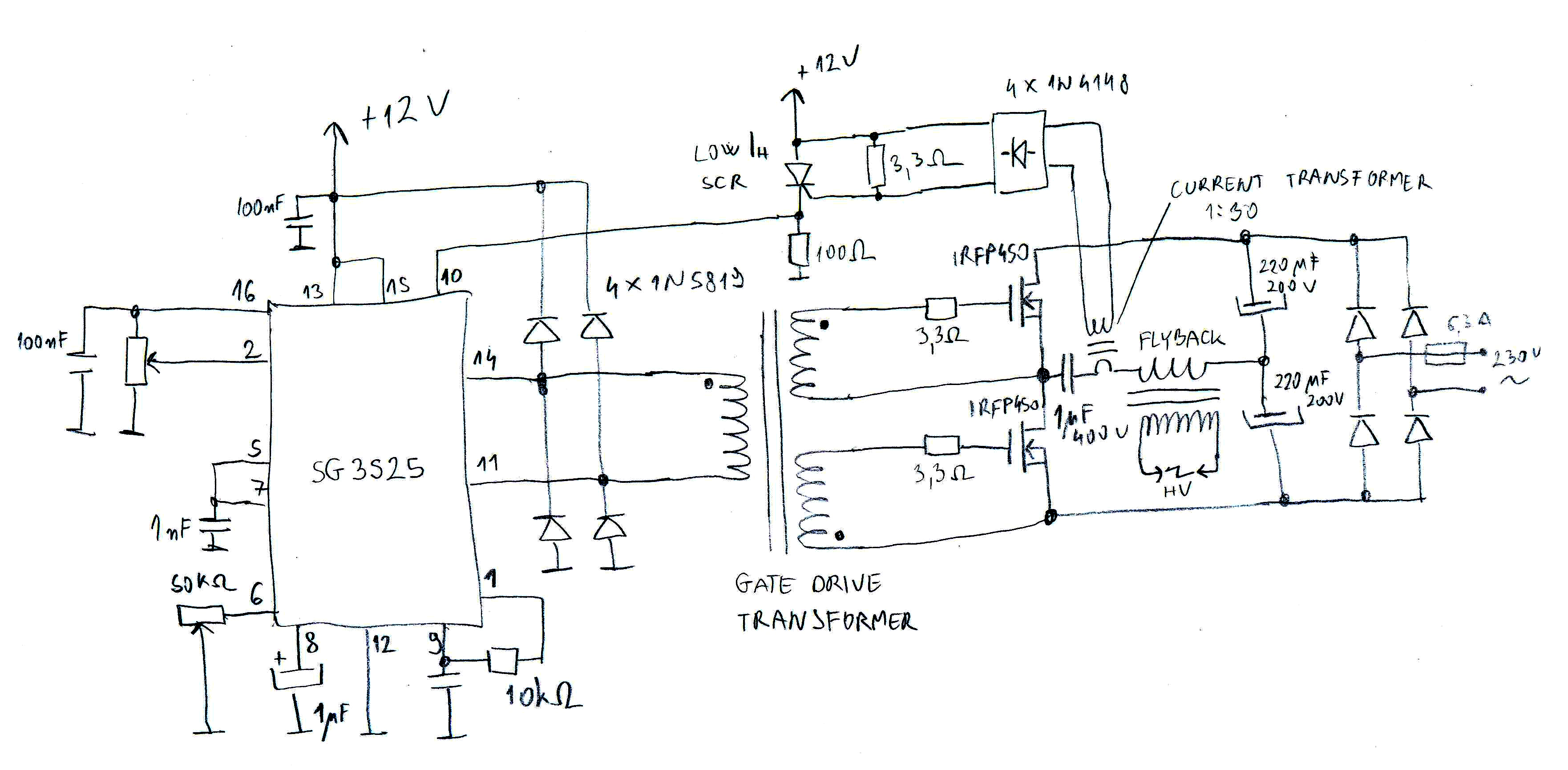
A flyback driver is a common high-voltage generator used by amateurs. It consists of a cathode-ray tube (CRT) TV high-voltage transformer driven by a high-frequency inverter to obtain a high-voltage output. The initial and simplest driver designs typically featured...
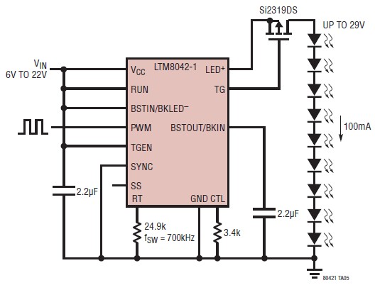
The LTM8042 integrates a boost power topology with a unique current loop to function as a constant-current source. The PWM input allows for LED dimming ratios of up to 3000:1, while analog dimming can be achieved with a single...
Circuit to control RC servos using 0-10V control voltage This circuit is designed to control RC servos by utilizing a control voltage range of 0 to 10 volts. The operation of the circuit is based on the principle of converting...
Most of the CDROMS available have an Audio-Out Output to either plug in the headphones or connect it to an amplifier. This circuit enables one to use the CDROM as a stand alone Audio CD player without the computer....