
Flyback Transformer Drivers
The flyback driver circuit operates by generating a high-frequency square wave that can effectively drive a flyback transformer. The 555 timer is crucial in this design, as it provides a stable oscillation frequency that can be adjusted by varying the resistance of the trimmers. The choice of capacitors for C3 directly influences the operational frequency of the circuit, allowing for versatility in application. The use of a totem pole configuration with the 2N3904 and 2N3906 transistors ensures that the gate of the MOSFET is driven efficiently, which is vital for minimizing switching losses and enhancing the overall performance of the circuit.
The IRF840 MOSFET selected for this application is well-suited for high-voltage applications due to its robust specifications. Its internal protection features, such as the zener diode, provide additional security against voltage spikes that can occur during operation, particularly during transient events. The inclusion of a snubber network serves to further mitigate these spikes, prolonging the lifespan of the components involved.
Overall, this flyback driver circuit demonstrates an effective approach to utilizing flyback transformers, providing a reliable solution for applications requiring high-voltage outputs. The careful selection of components and the thoughtful design of the circuit topology ensure that it can handle the demands of various flyback transformer configurations while maintaining efficiency and performance.This is an efficient flyback driver for modern cylindrical rectified television flybacks. Many sites doesn`t provide circuits driving these transformers, they simply say that they are bad. I don`t agree. In fact I built this circuit. I spent a lot of time for finding resonant frequency (around 15Khz) and duty cycle. These transformers best work at around 90% duty cycle. You may notice corona breakdown at terminals and pfffff sound (as well as the ozone smell) when adjusting the off time trimmer to near 500-300 ohms. Of course it will work for other tipes of flyback as frequency and duty cycle have a large range. Frequency range can be increased using multiposition switch for other values of C3 capacitor, for example 2 nF for 80KHz-200000KHz, but didn`t found flybacks with so high resonant frequencies, in addition with higher values of c3, eg 200nF, 2uF the frequency will drop making possible the use of ignition coils, and rectified power transformers @50Hz to charge high voltage electrolitic caps at 300-400V).
Unfortunately my ignition coil died because insulation breakdown (too long drawn arcs). The 555 is wired as an astable and the capacitor is charged only through the 4, 7Kohm trimmer (notice the diode) and discharged only through the 2. 2 Kohm trimmer, making the duty cycle full adjustable. The square wave is then feed in a totem pole made up of a 2N3904 and a 2N3906, which are cheap, and easy to find.
The totem pole ensures the gate being charged and discharged very fast (approx 50nS i think). The IRF840 is a cheap (i found it for 4euros) reliable and powerful power mosfet, it has current capability of 8 A continuous and 32A pulse, 800V drain source voltage, protecting internal zener diode. There is a snubbing network to ensure that voltage spikes are kept low (unless the insulation of the transformer start to leak) protecting both transistors and 555 IC.
100 ohm is a compromise between decay time and voltage spike. 🔗 External reference
Related Circuits
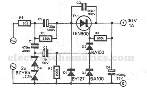
This transformerless power supply circuit is designed for medium current applications. During the negative half period, the capacitor C5 is charged to the peak voltage of the network. The positive half wave will trigger the thyristor, allowing the electric...
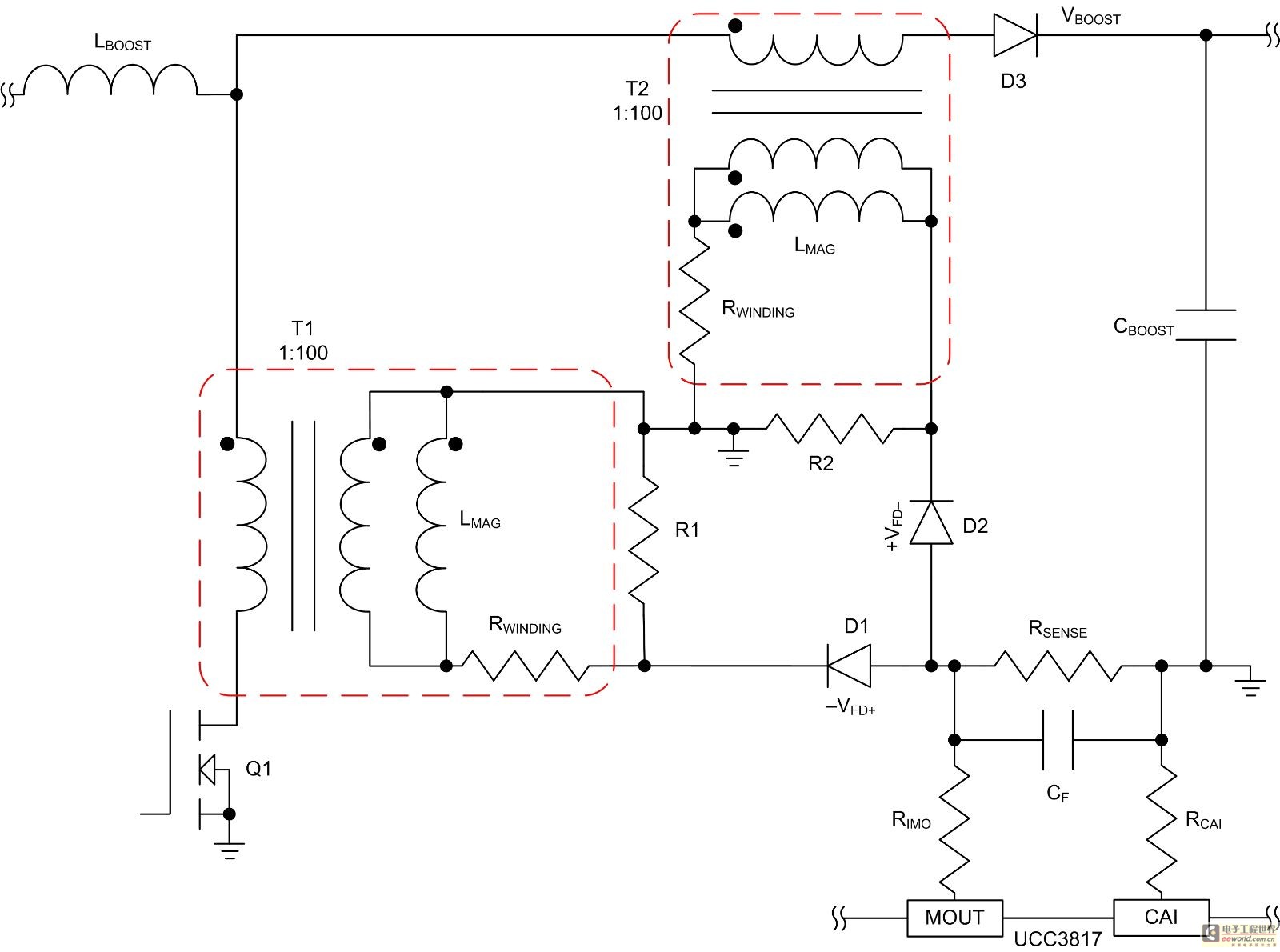
Mode control of the average current (CMC) is necessary to regulate the overall waveform of electric current during the rebuilding cycle. This text recommends selecting specific parameters related to the voltage transformer and outlines steps for designing a circuit...
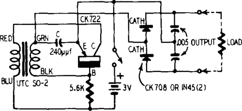
A battery is a low-impedance power source. It operates most efficiently and economically when providing low voltage at high current. Batteries serve as essential components in various electronic circuits, functioning as a reliable source of energy. Their low-impedance characteristic allows...
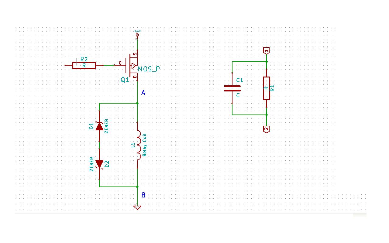
Although this may be a basic question, there is still some struggle with it. In this schematic, two zener diodes D1 and D2 are connected back-to-back across relay coil L1. The breakdown voltage (BVds) is -30V for Q1. The...
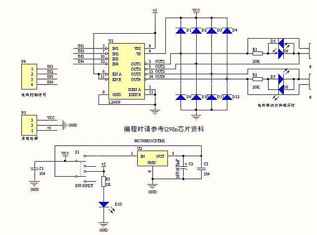
Arduino can drive various types of motors. However, the low-power signals from Arduino must control high-power circuits to operate the motors effectively. This document will provide examples of how Arduino can control different motor types and sizes. A motor...
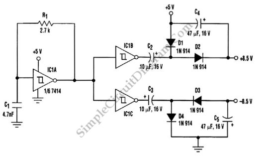
A DC to DC converter is required for a circuit board that operates solely on a +5V supply but needs to deliver dual-polarity outputs for several devices, such as operational amplifiers (op-amps) and digital-to-analog converters (DACs). To achieve dual-polarity supplies,...