
Servo Motor Control with PIC16F84
The described circuit utilizes a microcontroller, which serves as the central processing unit for controlling the servo motor. The 3-state switch is connected to the microcontroller's input pins, allowing users to select one of three positions for the servo motor. The switch typically connects to ground when not pressed, and when a state is selected, it sends a signal to the microcontroller.
The microcontroller interprets the switch's state and generates a corresponding pulse-width modulation (PWM) signal to control the servo motor. The PWM signal is crucial for determining the position of the motor. The signal's pulse width is generated by configuring a timer within the microcontroller, which can be programmed to output a high signal for the specified duration (1 ms, 1.5 ms, or 2 ms) based on the input from the switch.
The servo motor itself is powered by the VCC wire, while the ground wire completes the circuit. The position control wire receives the PWM signal from the microcontroller, allowing the servo motor to move to the desired position.
In terms of circuit connections, the VCC wire of the servo motor is connected to a suitable power supply, typically 5V, while the ground wire connects to the common ground of the circuit. The position control wire connects to the designated output pin on the microcontroller, which is configured for PWM output.
The source code written in PICBasic includes routines for initializing the microcontroller, reading the state of the switch, and generating the appropriate PWM signal based on the switch's position. This code is essential for the operation of the circuit, as it dictates how the microcontroller responds to user input and controls the servo motor accordingly. Proper implementation of this code ensures smooth and accurate positioning of the servo motor, making it suitable for various applications requiring precise control.This simple micro-control circuit controls a servo motor according to a 3-state switch. A servo motor acts as an actuator in 3 position. It has 3 wires, one for VCC, one for Ground and another one for position control. The last signal is a single pulse with variable width. The pulse width can vary between 1 and 2 mSec. An 1 mSec pulse width turns the motor axis in -45 degrees position. An 1. 5 mSec pulse width turns the motor axis in 0 degree position. A 2 mSec pulse width turns the motor axis in +45 degrees position. The following source code has been written in PICBasic: 🔗 External reference
Related Circuits
The preamp featured is very straightforward to make on the PCB, and has an innovative tone defeat function. Rather than completely disable the tone controls, they are massively de-sensitised, and when "defeated" have a maximum range as shown in...
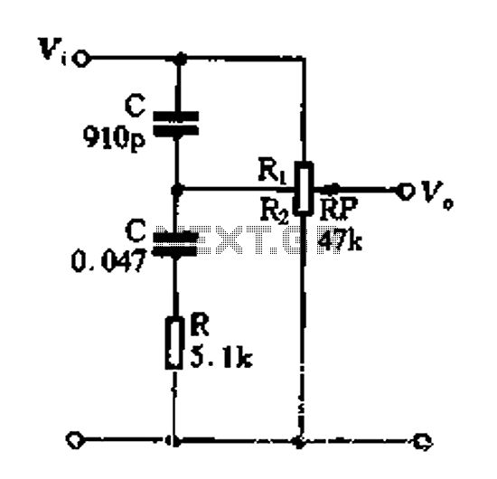
Figure 1-89 illustrates a loudness control circuit. A potentiometer is connected to ground, with 30% of the total resistance at the tap. When the slider arm is adjusted to the tap position, a midrange attenuation of 30 dB is...
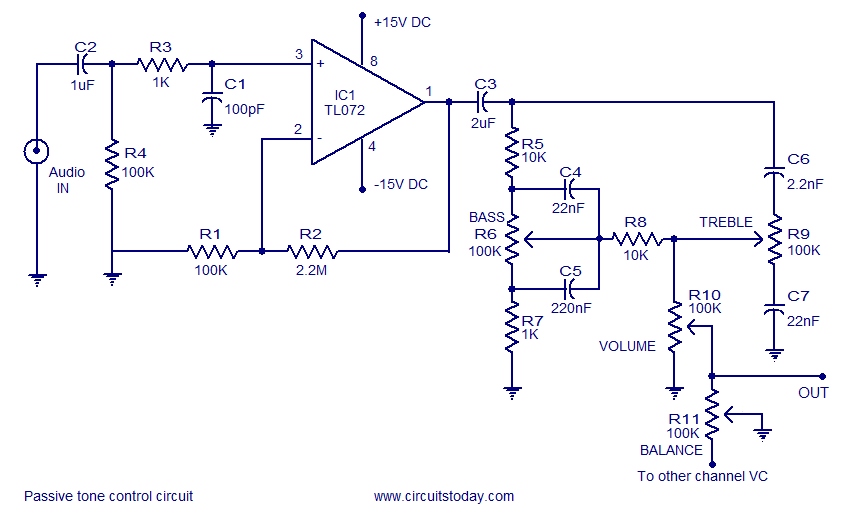
Tone control circuit utilizing an operational amplifier and a Baxandall passive tone control configuration. The overall gain is 25 dB, with a boost and cut capability of 20 dB. The circuit is powered by a dual 15V supply. The tone...
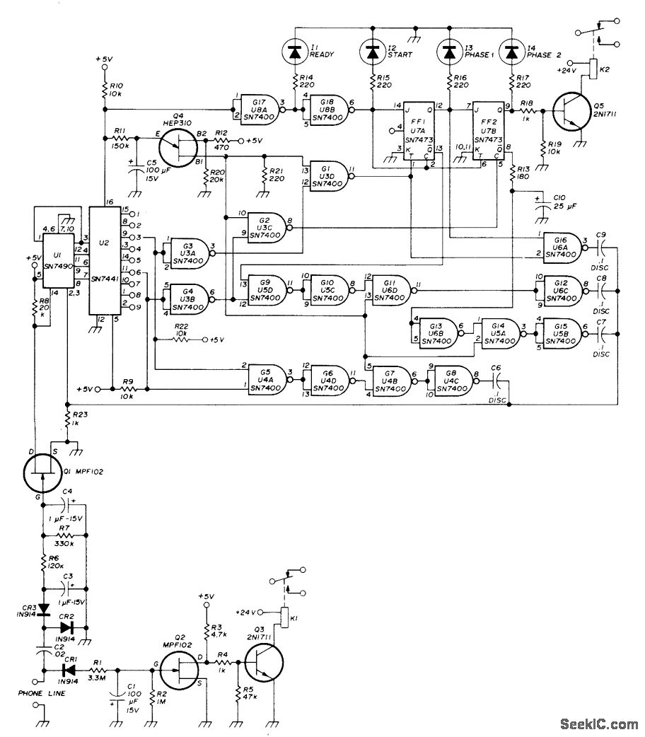
A repeater or other unattended equipment can be activated or deactivated using a standard telephone. The process involves calling the remote station, allowing it to ring three times, hanging up, waiting for 20 seconds, redialing the number, and letting...
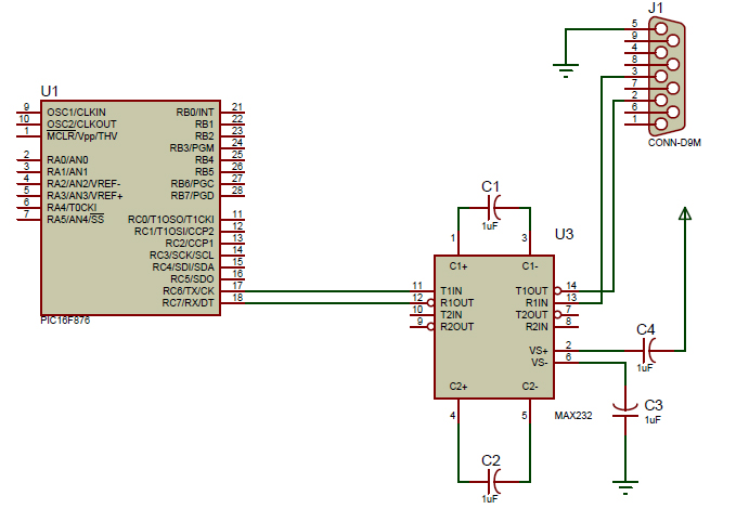
An introductory post on how to use serial communication in PIC Microcontrollers to send data to a PC. When considering serial communication, the primary thought is the transmission of data in a sequential manner. Until now, the focus has...

While developing an infrared (IR) extender circuit, a method was needed to measure the relative intensities of various infrared light sources. This circuit is the outcome of that research. A photodiode, specifically the SFH2030, is utilized as the infrared...