
PHONE RING REMOTE CONTROL
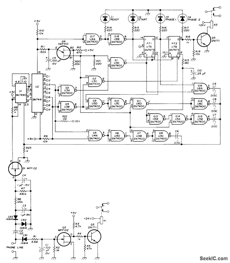
The described circuit serves as an automatic telephone controller for repeaters or similar unattended equipment. The operation begins with a telephone call to the remote station, which is designed to recognize a specific sequence of rings. The initial call allows the phone to ring three times, followed by a hang-up. After a 20-second interval, the caller redials and again allows the phone to ring three times. This dual-ring sequence is crucial for the system to identify the command to activate or deactivate the connected equipment.
The heart of the control mechanism lies in the decoder U2, which interprets the ring patterns. By moving two jumper wires to different outputs, the decoder can be programmed to respond to various ring combinations, enabling flexibility in operation. Relay K2 is selected based on the required operational mode—whether momentary, latching, or stepping—allowing for diverse control functionalities based on user needs.
Relay K1 plays a critical role in ensuring the integrity of the phone line. It acts as a safeguard; if the phone line is interrupted, the activation of the transmitter is prevented. This feature is essential for maintaining the reliability of the control system, particularly in situations where line disturbances could lead to unintended equipment activation.
Capacitor C1 is employed to maintain voltage during brief interruptions, ensuring that the circuit remains operational even when the phone line experiences ringing. This design consideration enhances the robustness of the control system, allowing it to function seamlessly during typical operational scenarios.
LEDs 11-14 provide visual indicators of the control sequence status, which is invaluable for troubleshooting and operational monitoring. These indicators allow users to quickly assess the system's state and diagnose any issues that may arise during operation.
The relays K1 and K2 are sensitive double-pole double-throw (DPDT) relays with 8000-ohm coils, selected for their responsiveness and reliability. Resistor R11 is incorporated into the circuit to set the desired timing parameters, ensuring that the system operates within predefined time frames for each stage of the control sequence.
Overall, this automatic telephone controller circuit exemplifies an efficient and reliable method for managing unattended equipment through standard telephone lines, providing flexibility and control tailored to user requirements.Repeater or other unattended equipment can be turned on or off with ordinary telephone Phone at remote station is called and allowed to ring three times Caller then hangs up, waits 20 s, redials number and lets it ring three times again, then hangs up. Circuit then performs desired control function. Any combination of rings can be used as long as total is less than nine. Decoder U2 is programmed by moving two jumper wires to various outputs of U2. Relay K2 is chosen to give desired momentary, latching, or stepping function. Relay K1 is used for validating phone line, If remote station keying voltage is taken through contacts of K1, interruption of phone line prevents activation of transmitter. C1 stores voltage during brief interruptions such as when phone is ringing. Article gives detailed explanation of ring-counting circuit. LEDs 11-14 indicate status of control sequence and aid in troubleshooting. K1 and K2 are sensitive DPDT relays with 8000-ohm coils. R11 is selected for desired time setting. -R. C. Heptig, Automatic Telephone Controller for Your Repeater, Ham Radio, Nov. 1974, p 44-48. 🔗 External reference
Related Circuits
The circuit flashes an LED when detecting an incoming call and is powered by a single 1.5V cell. It is designed to detect incoming calls in a cellular phone. This circuit utilizes a simple yet effective approach to alert users...
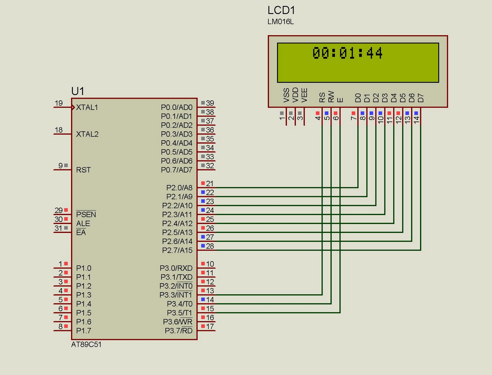
This project implements a real-time clock using the 89C51 microcontroller. The clock's data format is hours:minutes:seconds, which is displayed on a 16x2 LCD. The code has been tested and compiled using the Keil uVision compiler. The circuit diagram for...
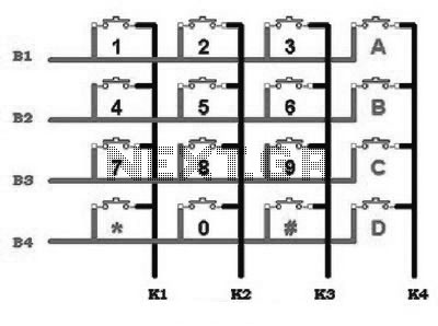
This includes an interface that is simple enough for mastery, as the keypad supports input facilities commonly used in Man-Machine Interface (MMI) applications. For example, various types of keypads can be found in the market. This discussion will focus...
The AVR 8-Bit RISC microcontroller from Atmel is a widely used microcontroller. This microcontroller integrates EEPROM, RAM, an Analog to Digital converter, numerous digital input and output lines, timers, UART for RS-232 communication, and various other features. An article...
The simplest solution for implementing joystick control for a robot is to program the actions in software on a microcontroller. However, many users prefer off-the-shelf components, thus this circuit is designed using diodes, resistors, transistors, and a FAN8200 motor...
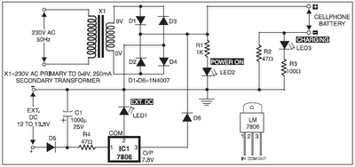
The 220V AC mains supply is downconverted to 9V AC by transformer X1. The transformer output is rectified by diodes D1 through D4 wired in bridge configuration, and the positive DC supply is directly connected to the charger's output...