
One instance of loudness control circuit

The loudness control circuit depicted in Figure 1-89 employs a potentiometer to adjust audio frequency response dynamically. The configuration allows for a variable resistance that influences the signal levels across different frequency bands, providing a tailored listening experience. The potentiometer is designed to offer a 30% resistance tap to ground, effectively creating a voltage divider that alters the audio signal's amplitude.
When the slider arm of the potentiometer is moved to the specified tap position, it results in significant attenuation across the frequency spectrum. The midrange frequencies experience a notable attenuation of 30 dB, which can effectively reduce the prominence of vocals and instruments that typically occupy this range, thereby allowing for a more balanced sound profile.
For lower frequencies, specifically at 100 Hz, a bass attenuation of approximately 23 dB is achieved. This reduction can be interpreted as a relative enhancement of 7 dB, meaning that the overall sound may be perceived as bass-heavy when compared to the original signal. This feature can be particularly useful in environments where low-frequency response is overwhelming or in need of adjustment.
In the higher frequency range, specifically at 10 kHz, the circuit provides an attenuation of about 27 dB, corresponding to a relative lift of 3 dB. This adjustment allows for fine-tuning of treble frequencies, which can be beneficial in reducing harshness or sibilance in audio playback.
Overall, this loudness control circuit is designed to enhance user experience by allowing for customized adjustments to the audio output, catering to personal preferences and varying listening environments. The careful calibration of frequency attenuation ensures a well-rounded sound profile that can adapt to different acoustic conditions.Figure 1-89 is an example of loudness control circuit. Potentiometer from the ground 30% of the total resistance at the tap. When the slide arm when screwed to the tap position , found midrange attenuation 30dB, 100Hz bass attenuation of approximately 23dB (ie, relative to enhance 7dB), treble lOkHz attenuation of about 27dB (ie, the relative lift 3).
Related Circuits
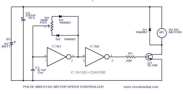
A simple PWM motor speed control circuit with a diagram and schematic for low power DC motors. This easy-to-make PWM DC motor controller is created using the IC CD40106B. The PWM (Pulse Width Modulation) motor speed control circuit utilizes the...

An RF power amplifier is an electronic amplifier used to convert a low-power radio-frequency signal into a larger signal of significant power, typically for driving the antenna of a transmitter. It is optimized for high efficiency, high output power...
NiCd battery charger schematic and description. This NiCd battery charger circuit can charge 12V, 6V, and 9V battery packs. The NiCd battery charger circuit is designed to efficiently charge nickel-cadmium (NiCd) batteries, specifically those with voltage ratings of 12V, 6V,...
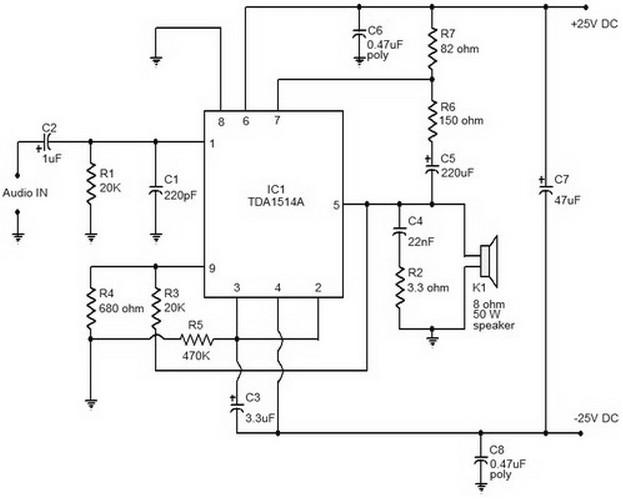
This document provides a circuit diagram of a car stereo. It includes a circuit diagram of a Class B 15 Watts audio amplifier designed using a dual op-amp and a transistor. The 15 W Class B audio amplifier circuit...
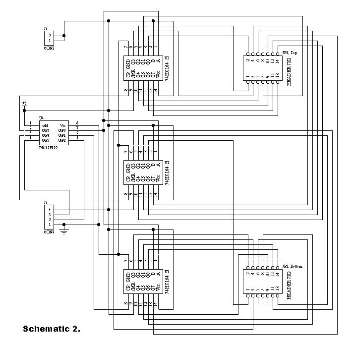
Communication with the MCP3028 ADC chip is achieved through a straightforward serial interface that adheres to the SPI protocol. The PIC16F84 or PIC16F628 does not possess a hardware SPI peripheral. However, a software-implemented SPI protocol can facilitate communication with...
This circuit is primarily designed to offer a microphone input for standard home stereo amplifiers. Utilizing a battery supply effectively eliminates the risk of low-frequency hum interference from the mains, and simplifies the connection to the amplifier by removing...