
Servo Motor Controller (PIC16F84)
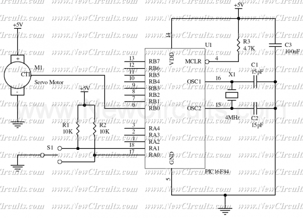
The described micro-control circuit is designed to operate a servo motor based on the input from a 3-state switch. The servo motor, which is an electromechanical device, is capable of precise angular positioning and is utilized here to achieve three distinct positions: -45 degrees, 0 degrees, and +45 degrees.
The servo motor consists of three primary connections: VCC (power supply), Ground, and a control signal wire. The control signal wire receives pulse-width modulation (PWM) signals that dictate the position of the motor. The PWM signal's pulse width is critical; it can vary between 1 millisecond (mSec) and 2 mSec. Specifically, a pulse width of 1 mSec corresponds to the -45 degrees position, 1.5 mSec corresponds to the 0 degrees position, and 2 mSec corresponds to the +45 degrees position.
The circuit's control logic is implemented using a microcontroller programmed with PICBasic. The code snippet indicates that the microcontroller is monitoring the state of the switch connected to one of its ports. The line `Symbol porta = 5` assigns the port number to a symbolic name, making it easier to reference in the code. The variable `b3 = 150` likely represents a delay or timing parameter used in conjunction with the PWM signal generation. The line `Peek porta, b0` suggests that the program is continuously reading the state of the switch connected to the specified port. The condition `If bit0 = 0` checks the state of the switch; if it is in the 'off' position, the subsequent actions (not fully shown in the provided snippet) would be executed.
In practice, the circuit would be powered by an appropriate voltage source connected to the VCC wire, while the ground wire ensures proper circuit completion. The control wire would receive PWM signals generated by the microcontroller based on the switch position, allowing for the precise control of the servo motor's angular position. This simple yet effective design is ideal for applications requiring basic angular positioning, such as robotics or automation systems.This simple micro-control circuit controls a servo motor according to a 3-state switch. A servo motor acts as an actuator in 3 position. It has 3 wires, one for VCC, one for Ground and another one for position control. The last signal is a single pulse with variable width. The pulse width can vary between 1 and 2 mSec. An 1 mSec pulse width turns the motor axis in -45 degrees position. An 1.5 mSec pulse width turns the motor axis in 0 degree position. A 2 mSec pulse width turns the motor axis in +45 degrees position. The following source code has been written in PICBasic: Symbol porta = 5 b3 = 150 start: Peek porta,b0 If bit0 = 0 Th 🔗 External reference
Related Circuits
This is a Class D audio amplifier circuit used to control the PWM motor speed. This circuit has two advantages for battery-powered portable devices. First, it provides high efficiency, which extends battery life. The Class D audio amplifier operates by...
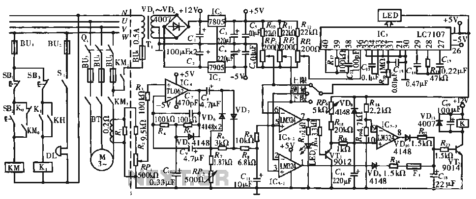
The circuit operates during standard inspection work by utilizing the voltage across resistor R2, which is connected to RP, to generate the input signal for IC4. Components R3 through Rg, along with capacitors C7 and C1, and diodes VD7...

A prerequisite for this article is that the GCC AVR programming environment is installed as described in the article "Programming the AVR microcontroller with GCC, libc 1.0.4." To avoid installation issues, using the AVR programming CD is recommended. When...
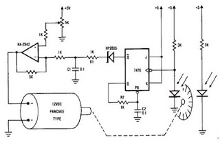
A simple encoder circuit for a DC motor can be constructed using the provided circuit diagram. The system includes the HA-2542 operational amplifier, a small 12 V DC motor, and a position encoder. During operation, the encoder generates a...
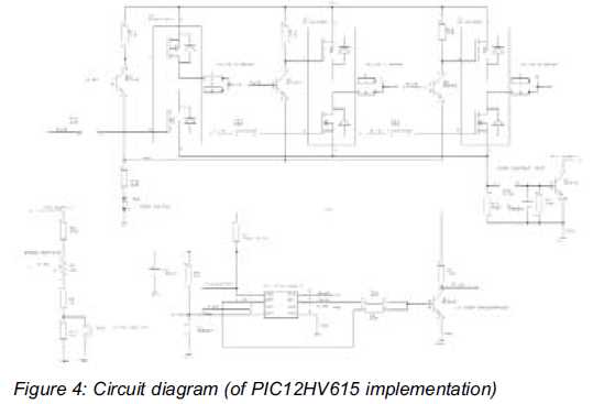
This article discusses a minimal resource microcontroller implementation for a three-phase Brushless DC (BLDC) motor, focusing on a closed-loop speed motor controller application based on a Microchip PIC12 device. It demonstrates how minimization techniques can reduce the number of...
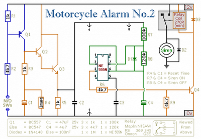
Any number of normally-open switches may be utilized. Install "tilt" switches that close when the steering is moved or when the bike is lifted off its side-stand or pushed forward off its centre-stand. Employ micro-switches to secure removable panels...