
Low Resource Microcontroller 3 Phase BLDC Motor Speed Controller
The accompanying block diagram illustrates a system employing a single Hall sensor for rotor position feedback (many systems typically use three for this function), a potentiometer for speed adjustment, a start/stop switch, a motor overcurrent trip, and a three-phase power bridge to drive the motor. The resulting number of independent connections to the microcontroller among the system's subcomponents totals 11 (five inputs and six outputs). However, minimization can be achieved if the microcontroller supports multifunction pins and widely available peripherals.
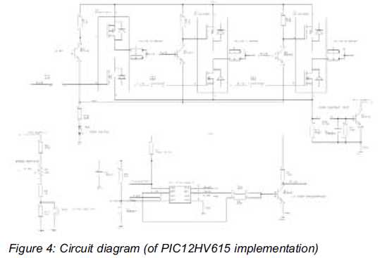
Considering the microcontroller output signals to the three-phase power bridge, if the BLDC six-step control algorithm is implemented, only two transistors are activated at any given time during normal operation—specifically, one high-side and one low-side transistor, which are driven in a non-complementary manner. The high-side and low-side transistors come from different half-bridge configurations and are operated in diagonal mode. This arrangement is beneficial for logic minimization because when two of the three high-side devices are off during operation, the third should be on. Consequently, the third high-side output signal can be reconstructed from the other two using a few resistors and a transistor inverter that connects to the third high-side power bridge input. This modification leads to a reduction in the required microcontroller outputs from six to five.
Regarding the five system inputs, which consist of the Hall sensor, potentiometer, motor current trip, and start/stop switches, various configurations are possible. The Hall sensor(s) are typically integrated into the BLDC motor assembly and often include circuitry for a digital interface to the microcontroller. This interface can utilize open-collector style transistor outputs, with a pull-up resistor provided at the external motor controller for signal detection. In this application, only one Hall sensor is necessary, and the PIC12F device family features a single digital input pin that can be designated for this purpose.
For the motor start and speed setting functionality, one of the three-phase power bridge high-side drive pins can be configured as an analog input upon power-up. This pin is connected to a resistive divider and potentiometer, allowing for speed setting prior to motor operation. Additionally, a start switch can be incorporated to reduce the speed setting below a minimum threshold, enabling the motor to start. In the analog input mode, although the connected high-side drive transistor is activated, this does not result in motor energization as all low-side drive transistors remain off during this initial setup.This article focuses on a minimal resource microcontroller implementation for a 3 phase BLDC motor, closed loop speed motor controller application based on a Microchip PIC12 device. It shows how minimisation techniques can reduce the number of I/O pins to just 6 for this type of application.
It assumes the reader understands the commutation sequen ce for the aforementioned type of motor. Just how small a microcontroller can control a 3 phase BLDC motor Well to answer that question requires the chip resources to be identified which align with the external BLDC motor control topology and functionality for the intended application. If at the outset we address the low cost volume market for speed control applications used in fans and pumps the problem narrows down.
In relation to this type of system there are those with sensor and sensor-less configurations (for determining rotor position) which both offer pros and cons but in terms of I/O count if the rotor position sensing can be done on one pin we are off to a good start. Also if multi function pins can be deployed for a simple user interface and logic minimization techniques can reduce the pin count further then the minimal resource map for a suitable device can be approached.
In Figure 1, the block diagram illustrates a system using a single Hall sensor for rotor position feedback (many systems use 3 for this purpose), a potentiometer for speed setting, a start and stop switch, a motor over current trip and a 3 phase power bridge to drive the motor. The resulting amount of independent connections to the microcontroller shown between the system sub components is 11 (5 inputs and 6 outputs).
However, minimisation can be accomplished if the microcontroller supports multi function pins and ubiquitous peripherals. Considering the microcontroller output signals to the 3 phase power bridge, if the BLDC six step control algorithm is deployed then only two transistors are ON at any time during normal running i.
e. one high side and one low side transistor and these are driven in non complementary fashion. So the high and low side transistors are from different half bridge configurations and are driven in the so called diagonal mode. This is advantageous from a logic minimisation perspective because when two of the three high side devices are OFF in run mode, the third should be ON.
Hence the third high side output signal can be reconstructed from the other two via a few resistors and transistor inverter which connects to the third High side power bridge input (ref Figure 4 - Circuit diagram). This leads to a reduction of microcontroller pins. So we have gone from a system requiring 6 outputs to one requiring 5. With respect to the five system inputs for a Hall sensor, potentiometer, motor current trip and start/stop switches there are various possibilities.
Firstly the Hall sensor(s) are commonly built into the BLDC motor assembly and these tend to have also integrated circuitry for a digital interface to the microcontroller. This can take the form of open collector style transistor outputs and a pull up resistor is provided at the external motor controller end for signal detection.
In this application one Hall sensor is required and the PIC12F device family feature one digital input only pin that can be used for this purpose. For the motor start and speed setting function, at power up one of the 3 phase power bridge high side drive pins can be configured as an analogue input.
This pin is connected to a resistive divider and potentiometer. Hence before the motor is run the speed can be set and read. In addition the addition of a start switch which can reduce the speed setting below a minimum can also enable motor starting. In this analogue input mode, although the connected high side drive transistor is turned on this does not result in motor energization as all the low side drive transistors are off at this time.
Subseque 🔗 External reference
Related Circuits

Capacitor start single-phase induction motor circuit configuration, in order to form a two-phase rotating magnetic field, starting winding and capacitor in series, the same magnetic field can be formed automatically. The capacitor start single-phase induction motor utilizes a specific circuit...
There was difficulty in understanding that the Source pin connects to low voltage (source of electrons) and the Drain pin connects to high voltage (absorbs electrons). This concept is fundamental to basic electricity, but it required some time to...
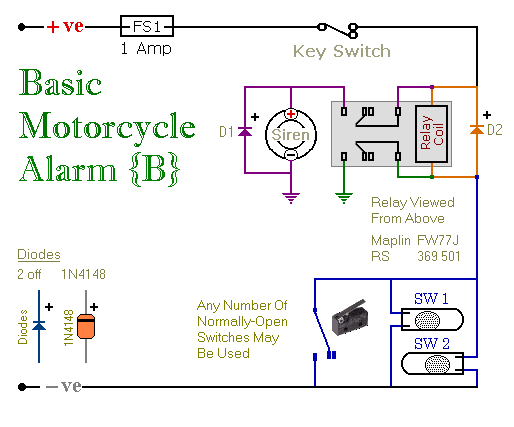
These are two easy-to-build relay-based alarms. They can be used to protect a motorcycle, but they have many additional applications. When using relays with 6-volt coils, they can safeguard a classic bike. Both alarms are compact, with completed boards...
Constantly changing light and sound analog controller circuit 02 The circuit described is an analog controller designed to modulate light and sound in a dynamic manner. It typically utilizes components such as operational amplifiers, resistors, capacitors, and transistors to achieve...
A circuit is being designed to drive a 4x7 segment display using a PIC microcontroller. The previous implementation utilized four pins to control each of the four digits individually, with a sequential activation method. The designer aims to simplify...

A current source that achieves a resolution as low as 10 pA is beneficial in applications requiring precise, low-value currents. When the circuit directs current into the ground, the output remains within 2% of the ideal current across the...