
servo motor pot control
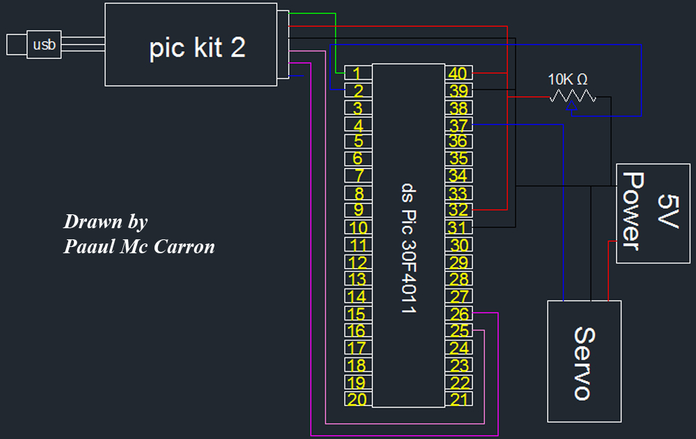
A servo motor operates based on a feedback control system, which typically includes a potentiometer to monitor the angle of the motor shaft. The control signal, usually a PWM (Pulse Width Modulation) signal, determines the position of the motor. The width of the pulse corresponds to the desired angle, and the servo adjusts its position accordingly to match this input.
Servo motors are commonly used in applications requiring precise control, such as robotics, radio-controlled vehicles, and automation systems. They are available in various sizes and torque ratings, allowing for flexibility in design based on the specific requirements of the project. The typical range of motion for most standard servo motors is between 0 to 180 degrees, but there are continuous rotation servos available that can rotate indefinitely in either direction, though they do not provide positional feedback.
When integrating a servo motor into a circuit, it is essential to consider the power supply requirements, as servo motors can draw significant current during operation. Additionally, the control circuitry must be designed to handle the PWM signal accurately to ensure smooth and responsive movement. Overall, the use of a servo motor adds a high level of precision and control to various electronic projects.As part of the module one of the motors we will be using is a servo motor.A servo motor is a small motor that you can position at any angle very accurately. It contains internal circuits that will automatically maintain that particular angle. However, you cannot do full revolutions with a servo. You are restricted to.. 🔗 External reference
Related Circuits
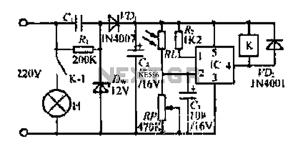
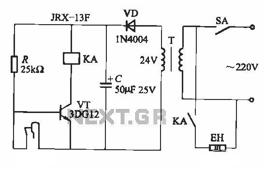
At dawn, light illuminates the photosensitive resistor RL, causing its resistance to decrease. This switch IC (2) exhibits a high electrical footprint. When light is present, the relay K does not activate. At night, in the absence of light,...
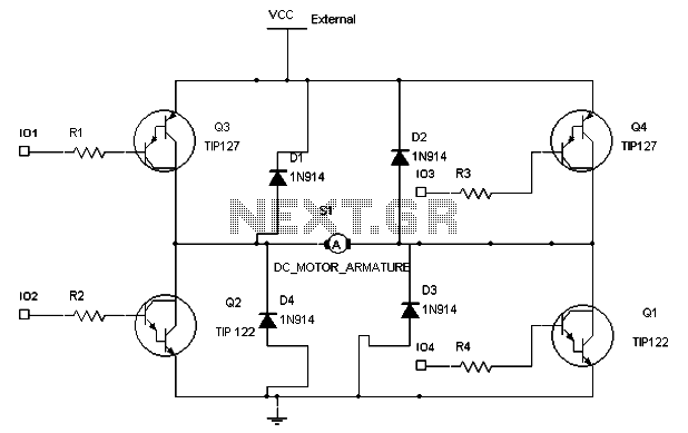
To maintain a constant speed of the motor under varying load conditions, a control application circuit is required. An H-Bridge circuit can be utilized to manage both the speed and direction of the motor. The accompanying diagram illustrates the...

A servo tester circuit has been built as shown. The only observable action is for the servo to twitch when the power is switched on. There is no clear reason for its failure to operate correctly. Suggestions for troubleshooting...
This project provides a simple temperature-controlled fan. If the difference between the actual temperature and the user-defined temperature is significant, the fan will operate. The temperature-controlled fan circuit utilizes a temperature sensor, a microcontroller, and a fan motor to regulate...
A fluorescent starter bimetal can be utilized as a temperature sensing element for thermostatic control. This component consists of a double metal sheet designed for temperature sensing, resulting in a simple circuit that is easy to manufacture, although it...

The optical control circuitry for high-performance street lighting is depicted in the figure. The circuit comprises a photoelectric conversion element, specifically a Light Dependent Resistor (LDR), a comparator circuit using an integrated circuit (IC1) which is a 555 timer,...