
servo tester

The servo tester circuit is designed to provide a simple means of testing servo motors by generating a control signal. The core component of the circuit is the 555 timer IC, configured in astable mode to produce a pulse-width modulated (PWM) signal. This PWM signal is responsible for controlling the position of the servo motor.
The circuit typically includes a power supply, often a battery or a regulated DC power source, which powers the 555 timer and the servo. The output of the 555 timer connects to the signal pin of the servo. The circuit may also incorporate capacitors to stabilize the power supply and reduce noise, which can interfere with the servo's operation.
In terms of connections, the servo motor usually has three wires: one for power (positive), one for ground (negative), and one for the signal. Proper wiring is essential to ensure that the servo receives the correct voltage and control signals. The polarity of the connections must be observed to prevent damage to the servo.
To further enhance the circuit's reliability, it may be beneficial to include bypass capacitors close to the power pins of the 555 timer and the servo. These capacitors can help filter out high-frequency noise that could cause erratic behavior in the servo.
In conclusion, while the circuit's basic operation is straightforward, attention to detail in assembly and component selection is crucial for optimal performance. Testing with an oscilloscope can help diagnose any issues by visualizing the PWM signal and ensuring it meets the required specifications for the servo being used.Built servo tester cicuit as shown - only action is for the servo to twitch when power switched on, cannot see any real reason why wont work - ideas anyone I haven`t built this circuit yet so I can`t comment on the circuits efficacy. I do have some experience of using servos in radio controlled models, both aircraft and cars. Whenever I have experienced servo twitch it has been caused by some form of interference, not necessarily from your circuit but signals from things like refrigerators and the like when tested indoors and in close proximity. The servo tends to glitch and twitch if their is a fault in the rx. Sometimes the servo itself can be faulty. Try another servo. My bet is that its noise from either external components or maybe the circuit itself. I have had to install ceramic capacitors to small electric motors before now to cut the excess noise that can affect a servo.
That`s my best guess, hope it helps or at least points you in the right direction. I haven`t built this circuit yet so I can`t comment on the circuits efficacy. I do have some experience of using servos in radio controlled models, both aircraft and cars. Whenever I have experienced servo twitch it has been caused by some form of interference, not necessarily from your circuit but signals from things like refrigerators and the like when tested indoors and in close proximity. The servo tends to glitch and twitch if their is a fault in the rx. Sometimes the servo itself can be faulty. Try another servo. My bet is that its noise from either external components or maybe the circuit itself. I have had to install ceramic capacitors to small electric motors before now to cut the excess noise that can affect a servo.
That`s my best guess, hope it helps or at least points you in the right direction. Konrad - thanks for the thought, but I am an experienced RC aeromodeller and in fact used to own my own model shop. I can guarantee that it is not IF causing the twitch which is exactly the same as when most standard RC RX`s are switched on.
I am at a loss as to next move, I do know how to handle IC`s but this is my first use of a 555 and need someone to point me in a likely direction - please note I have a scope available so can check on what really should be happening. I think this will be my next build. Perhaps you can help me with a question I have regarding the circuit. Into what and where exactly do you plug the servo connector From my experience these can be of a slightly different design, so one plug does not fit every rx.
Surely you don`t have to take the plug of the servo to get it into the circuit. Perhaps I`m missing something from the schematic. A case of `can`t see the wood for the trees`. Hi Konrad - I used a female connector from an unused servo extention lead - simply cut the lead in half and soldered the lead into the respective holes on my circuit board, (please note you can buy female only leads from the better model shops or one of the bigger electronic suppliers), I simply had a lead handy. You are correct saying that there are differences in some servo connections - if you are using either Futaba or JR compatible leads then the circuit shows the correct layout black(brown)= neg.
red=pos. white(yellow, orange)=signal. The positive is usually the centre lead in a flat cable. Also the JR and Futaba plugs are not physically identical even though they are electrically the same. I remove the small ridge on a Futaba plug carefully, it will then fit either system and you only have to make sure that it`s the right way round!
A few of the less popular brands use all black leads, personally I refused to stock these when I had my shop as they were more prone to problems - the only reliable way to check these black leads is to look at the same manufacturers RX and note which lead is which. Finally, if you haven`t got a suitable lead, then providing you are happy to remove the servo plug, 🔗 External reference
Related Circuits

The tester provides an audible indication, eliminating the need for the user to directly observe a meter reading. Additionally, the current and voltage output of the tester are strictly limited, with a maximum of 0.6 volts DC and 3...

Varies the speed and direction of a 5-amp reversible series AC motor according to a DC control signal. The polarity of the control signal determines the direction of rotation. A gain potentiometer adjusts the slope of the speed versus...

Vasilis Stergiopoulos has developed an RJ45 LAN cable tester. The circuit was initially designed to utilize a 555 timer and a 4017 decade counter IC, but Vasilis has released a schematic and assembly source code for implementing the Attiny2313...

The telephone line tester comprises a meter used to measure line voltage in both the on-hook and off-hook states, three resistors (including one variable resistor), a pushbutton switch, and a modular telephone connector. When the circuit is connected to...
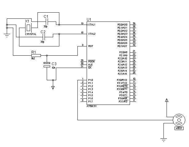
The control signals for the motor's rotation are generated by an 8051 microcontroller. For foundational concepts and information about a servo motor, refer to the article on Servo Motors. The source code utilized is based on the AT89S51 microcontroller....
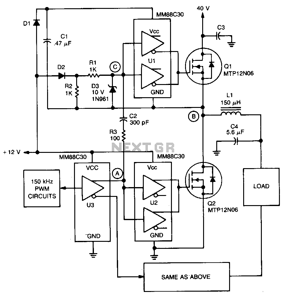
A significant feature of the PWM servo amplifier is the removal of a pulse transformer. A 150 kHz pulse-width modulated signal is applied to U3, with its complementary outputs directed to identical circuits to drive the load. When point...