
Set Timing Calculator With The LM555IC
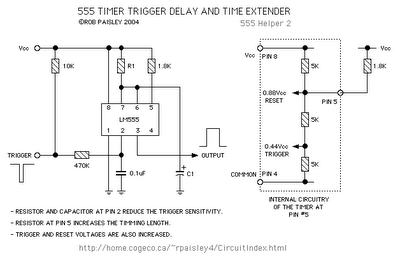
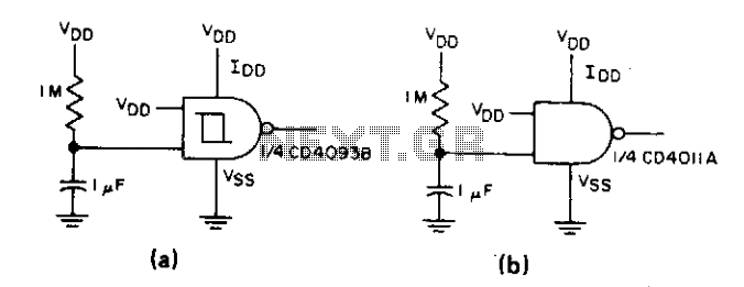
The Set Timing Calculator Circuit utilizing the LM555 integrated circuit (IC) is designed to generate precise time delays based on external component values. The LM555 is a versatile timer IC that can be configured in various modes, including monostable and astable operation. In the monostable configuration, the circuit generates a single output pulse of a specific duration upon receiving a trigger signal.
In this circuit, the timing interval is determined by the resistor (R) and capacitor (C) values connected to the LM555. The time delay (T) can be calculated using the formula:
T = 1.1 × R × C
Where:
- T is the time delay in seconds,
- R is the resistance in ohms,
- C is the capacitance in farads.
The components selected for R and C will dictate the length of the delay. For example, if a resistor of 100 kΩ and a capacitor of 10 µF are used, the calculated delay would be approximately 1.1 seconds.
The circuit typically includes a trigger input that activates the timing sequence. When a low voltage signal is applied to this input, the output of the LM555 goes high, and the timing cycle begins. After the designated time interval, the output returns to its low state. This behavior makes the circuit suitable for applications such as timers, pulse generators, and delay circuits in various electronic projects.
Additional components may include diodes for protection against reverse polarity and capacitors for noise filtering to ensure stable operation. The circuit can be powered using a standard DC voltage supply, typically ranging from 5V to 15V, depending on the specific requirements of the application. Proper layout and connection of components are crucial for optimal performance and reliability of the timing calculator circuit.The following circuit shows about Set Timing Calculator Circuit. This Circuit based on the LM555IC. Features: provide a delay of approximately .. 🔗 External reference
Related Circuits
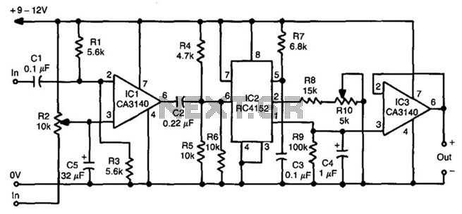
This frequency-to-voltage converter facilitates the calibration of cassette deck speed. It generates a stable 1 kHz tone on the cassette deck and monitors the frequency through the converter. Playback of the tone allows for adjustments to the motor speed...
This project utilizes a single tube, specifically the 13EM7, which contains two distinct triode structures. The first structure is compact and provides substantial signal gain but limited power, making it suitable for a preamplifier stage. The second structure is...
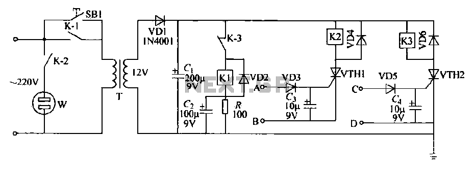
This schematic circuit features two alarm outputs controlled by a timer using thyristors. The system can be turned on or off and will shut down after the power supply is interrupted. It employs a transformer on the primary side...
This type of reset pulse is ideally provided by this circuit. Due to the high input impedance of the Schmitt trigger, long reset pulse durations can be achieved without the excess dissipation that occurs when both output devices are...
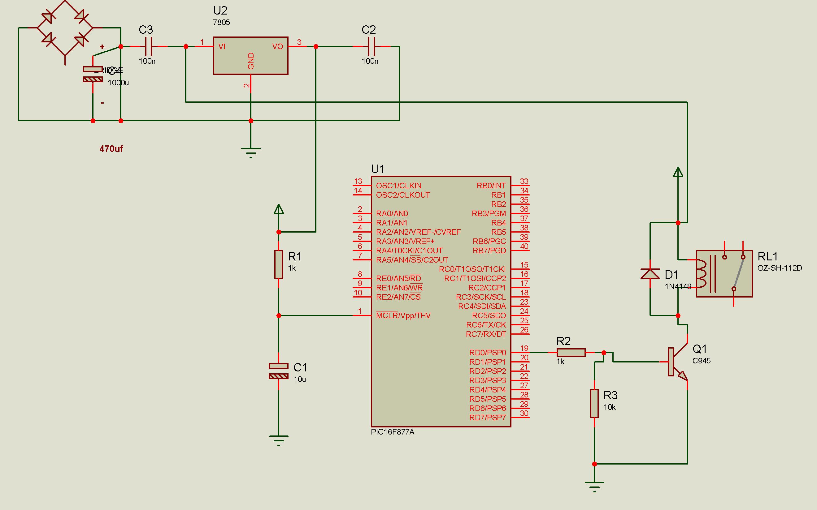
Connect a relay with a PIC microcontroller, and whenever a load is applied to the relay contacts, the PIC16F877A resets. This issue has been partially resolved by triggering another relay from the basic relay attached to the PIC, but...
The PIC18F4550 chip features more capabilities than the PIC16F, including a USB communications module, which adds some complexity. The first consideration is which chip to order. The PICSTART Plus programmer is compatible with the 40-pin PIC18F4550-I/P chip. Variants of...
Warning: include(partials/cookie-banner.php): Failed to open stream: Permission denied in /var/www/html/nextgr/view-circuit.php on line 713
Warning: include(): Failed opening 'partials/cookie-banner.php' for inclusion (include_path='.:/usr/share/php') in /var/www/html/nextgr/view-circuit.php on line 713