
The MiniBlok SET Amp

The 13EM7 tube is a versatile component in audio amplification circuits, effectively combining the roles of preamplifier and power amplifier. The preamplifier section, characterized by its high gain, is responsible for boosting low-level audio signals to a suitable level for further amplification. The power amplifier section, with its capacity to handle higher currents, drives the output to a speaker, ensuring adequate sound levels. The design's reliance on a voltage doubler circuit is crucial for generating the necessary grid bias, which influences the tube's operating point and overall performance. The use of a transformer to step down the AC voltage for filament heating is a standard method in tube circuits, as it ensures the tube operates efficiently without introducing significant hum into the audio signal.
The optional pilot lamp circuit adds a visual indicator of power status, enhancing usability. The careful selection of components, such as diodes and capacitors in the voltage doubler, ensures that the circuit operates reliably while maintaining the desired performance characteristics of the tube. Overall, this project exemplifies the effective use of the 13EM7 tube in audio applications, highlighting its potential for producing high-quality sound in various settings.This project uses just one tube. However, the tube chosen (13EM7) actually contains two separate triode structures. One is physically quite small, and is capable of a large signal gain but little power. It therefore makes an ideal preamplifier stage. The other section is larger, and ha s a lower voltage gain, but is capable of a significant amount of current. It therefore can deliver up to about two watts of power into a speaker load under the appropriate conditions. This tube was originally designed to be used in television sets. The small, high-gain section was typically used as the vertical oscillator, and the larger section as the vertical output stage.
However, it also makes a splendid audio tube. If you think about it, linearity is no less critical in television sets than it is in high-fidelity audio. At the same time, there isn`t the "mystique" around television tubes that there is around so-called "audio" devices, so the price is a lot more reasonable than otherwise quite similar tubes such as, say, the Type 45.
There are a few different variants of this tube which can be used. The 13EM7/15EA7 is functionally identical to the plain 13EM7. If you`re buying a tube for this project, either variant will be fine. If you have a "junk box" of tubes, but don`t have a 13EM7, you might have a look to see if you can find a 10EM7. This is the same tube, but with a lower-voltage filament. It can be used in this design if a filament dropping resistor is added (details later). The 6EM7 or 6EM7/6EA7 could conceivably be used also, but will be a bit more involved; for this reason this option is suggested only for more experienced tube equipment builders.
Similarly, there are other tubes such as 13FM7 which would work in this kind of circuit, but would require the harder-to-find 12-pin "compactron" socket, whereas the *EM7 series takes the more common "octal" socket. There are essentially three separate power supplies required, as suggested by the three battery symbols in the basic common-cathode amplifier circuit on the previous page.
The first (usually called the "A" supply) is to heat the filament of the tube, the second provides the high voltage for the plate circuits (the "B" supply), and the third provides the negative grid bias for the power amplifier ("C" supply). Incoming power from the 120 VAC power line is switched by on-off switch S1, and thence applied to step-down transformer T1.
This is rated at 12. 6 volts at 2 amperes, and in practise will supply very close to 13 volts at its secondary. This is what heats the tube`s filament. Note that we don`t bother converting to DC, in this application an AC heater is just fine because 1) we`re not dealing with extremely high gain, and 2) the 13EM7`s indirectly-heated cathode is naturally highly immune to AC hum. At the same time, this 13 volt AC supply is connected to the network consisting of diodes D3 and D4, and capacitors C4 and C5.
This is a "voltage doubler" circuit. During positive half-cycles, C4 is charged up to the peak value of the incoming AC voltage (about 13 volts times 1. 4, or 18 volts). During negative half-cycles, this charged capacitor is essentially placed in series with the incoming supply, causing capacitor C5 to about twice the peak value after only a few cycles.
This forms our -35 volt grid bias supply. An optional pilot lamp network consisting of LED (light-emitting diode) D5, resistor R5, and diode D6 can be also connected to the 13 volt line. Resistor R5 limits the maximum current to a safe level for the LED, and D6 prevents excessive reverse voltage during negative half-cycles.
Finally, the secondary of T1 is also connected to the low-voltage winding of a similar transformer T2 (12. 6 volts at 1 ampere). T2 steps the 13 volts back up to approximately 110 volts AC. From there, another voltage doubler (this time with a slightly diffe 🔗 External reference
Related Circuits

An RF power amplifier is an electronic amplifier used to convert a low-power radio-frequency signal into a larger signal of significant power, typically for driving the antenna of a transmitter. It is optimized for high efficiency, high output power...
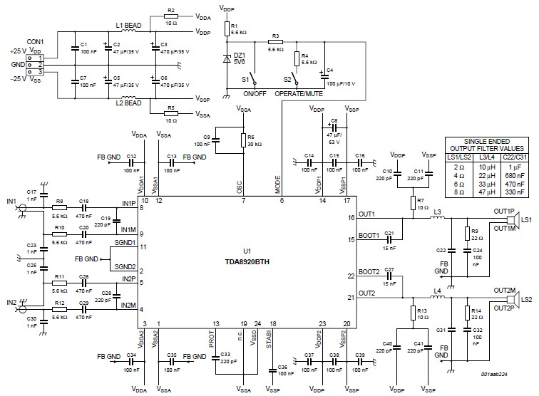
This high-power Class D audio amplifier electronic project is designed using the TDA8920BTH audio power amplifier IC. This power amplifier IC offers very high efficiency with minimal dissipation, yielding significant output power. The typical output power is 200 watts...
The TS4962 is a differential class-D BTL power amplifier capable of driving up to 2.2W into a 4-ohm load and 1.4W into an 8-ohm load at 5V. It achieves outstanding efficiency (typical 88%) compared to standard AB-class audio amplifiers....
This circuit is a class AB stereo audio power amplifier designed by Quasar for high-fidelity applications using a TDA2005 module. It is straightforward to construct and requires a minimal number of external components. The module includes output current protection...
This design is based on an 18 Watt audio amplifier and was developed primarily to meet the needs of users who are unable to find the TLE2141C chip. It utilizes the widely available NE5532 dual integrated circuit; however, its...
This circuit is an enhanced version of the circuit depicted in Figure 8-21. The hysteresis effect has been mitigated through the incorporation of two diodes and a 5.1 kΩ resistor. An RC network is connected across the TRIAC, functioning...