
SH-841 ASIC holiday lights

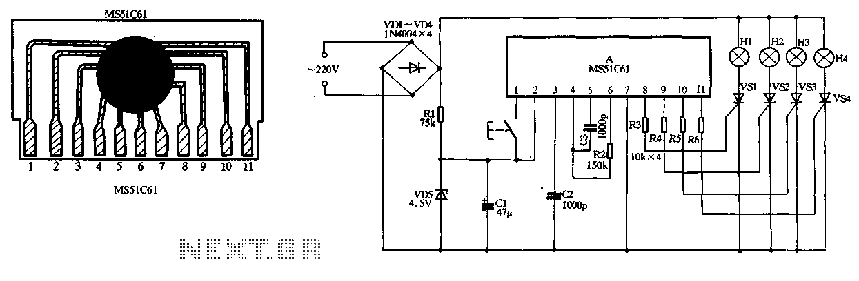
The circuit design described in Figure 2-78 serves as an effective holiday lights controller, integrating both visual and auditory effects. The SH-841 microcontroller is the heart of the system, managing the operation of the light strings. The SCRs (Silicon Controlled Rectifiers) VS1 to VS4 are crucial for controlling the flow of current to the light strings H1 to H4. These SCRs allow for the modulation of the light output, creating a flashing effect synchronized with a music signal.
The AC power supply is converted to a usable DC voltage through the bridge rectifier composed of diodes VD1 to VD4. This configuration ensures that the circuit can handle both halves of the AC waveform, providing a smooth DC output. Resistor R1 is used to step down the voltage to a safe level for the subsequent components. Diode VD5, in conjunction with capacitor C2, serves to filter out any ripple from the rectified voltage, ensuring a stable DC supply for the circuit's operation.
The audio component of the circuit is facilitated by the amplifying transistor VT, which boosts the music signal output. This amplified signal is then used to drive a piezoelectric ceramic sheet B, which converts the electrical signal into sound. The integration of sound with the visual elements of the holiday lights enhances the overall experience. The potentiometer RP provides user-adjustable control over the sound volume, allowing for customization based on user preference or ambient conditions.
Overall, the circuit exemplifies a well-designed integration of lighting and sound, suitable for festive decorations and events. The combination of SCRs for light control and a transistor for sound amplification showcases a practical application of electronic components in creating an engaging user experience.Figure 2-78 is SH-841 as the core device made holiday lights controller. By SCR VSl ~ VS4 to drive light string H1 ~ H4 flashes. Manifold operating voltage by AC by VD1-VD4 bri dge rectifier, Rl buck, VD5 filter regulator and C2 obtained. Manifold 2 feet of the music signal output by the amplifying transistor VT to drive the piezoelectric ceramic sheet B made sound. Adjustment potentiometer RP can control the sound volume.
Related Circuits
The study of electricity involves several key terms that explain the behavior of electrical charge. Electrical charge and its related phenomena are fundamental to the world we inhabit. The understanding and application of electricity have significantly contributed to the...
The 8051 microcontroller features a transmit channel and a receive channel for serial communication. The transmit data pin (TXD) is designated as P3.1, while the receive data pin (RXD) is located at P3.0. The serial signals on these pins...
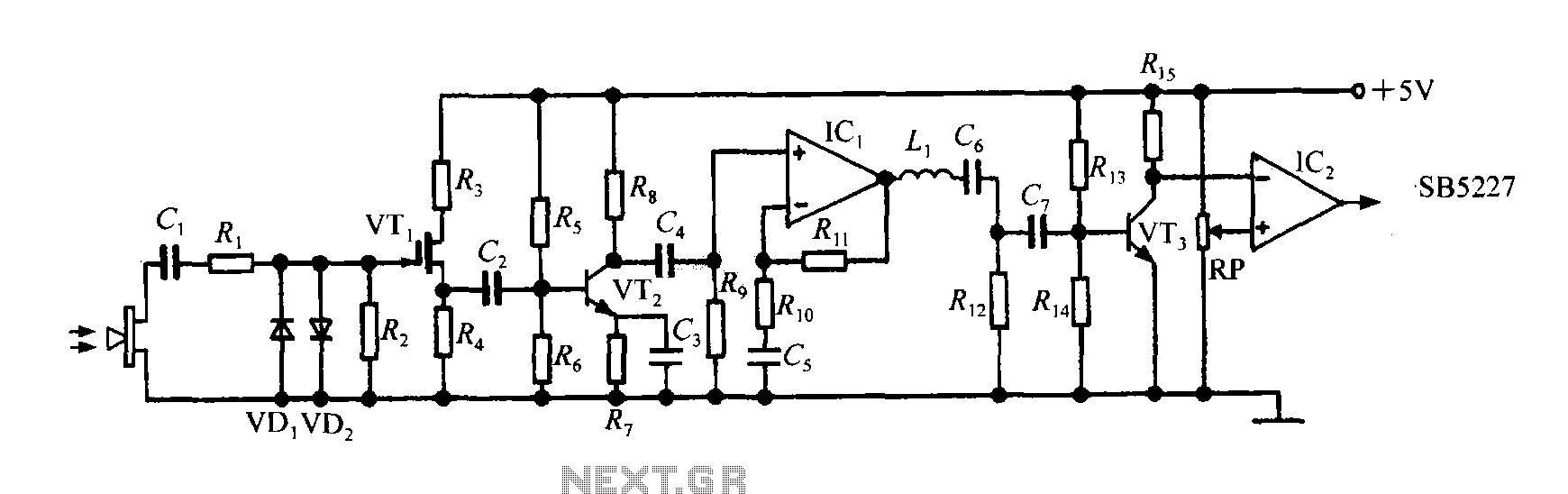
The SB5227 ultrasonic signal output is very weak and must be amplified via a power amplifier for effective transmission. A typical transmission circuit is illustrated in the accompanying figure. The SB5227 ultrasonic signal is sourced from output pin 10,...
This simple circuit drives six LEDs in a "Knightrider scanner mode." Power consumption primarily depends on the type of LEDs used, particularly when employing a 7555 (555 CMOS version). The circuit operates by sequentially illuminating the LEDs to create a...
The circuit utilizes a 220V AC input, which is converted to DC using a VD1-VD4 bridge rectifier. This rectified voltage is used to power four lights (H1 to H4). The circuit also includes a resistor (R1) for voltage limiting...

A basic LED driver circuit consists of a 5-volt power source, a 2 kΩ potentiometer, and an LED. The LED is forward biased, with the manufacturer specifying a maximum current rating of 20 mA at a diode voltage drop...
Warning: include(partials/cookie-banner.php): Failed to open stream: Permission denied in /var/www/html/nextgr/view-circuit.php on line 713
Warning: include(): Failed opening 'partials/cookie-banner.php' for inclusion (include_path='.:/usr/share/php') in /var/www/html/nextgr/view-circuit.php on line 713