
Basic Led circuit driver

The LED driver circuit operates by regulating the current flowing through the LED to ensure it remains within safe limits while providing the desired brightness. The 5-volt power source serves as the primary supply for the circuit. The inclusion of a 2 kΩ potentiometer allows for adjustable current control, enabling users to vary the brightness of the LED according to their requirements.
In this configuration, the LED is forward biased, meaning that the anode is connected to the positive terminal of the power source, and the cathode is connected through the potentiometer to ground. When the circuit is powered, the voltage across the LED will reach approximately 1.9 volts when operating at the specified maximum current of 20 mA.
To calculate the appropriate resistance setting on the potentiometer, Ohm's Law can be applied. The total voltage across the circuit is 5 volts, and the voltage drop across the LED is 1.9 volts, leaving a voltage drop of 3.1 volts across the potentiometer. The required resistance can be calculated using the formula R = V/I, where V is the voltage across the potentiometer and I is the desired current. Substituting the values gives R = 3.1V / 0.02A = 155 Ω.
This calculation indicates that the potentiometer should be set to approximately 155 Ω to achieve the desired current. However, since the potentiometer has a maximum value of 2 kΩ, it provides a wide range of adjustability, allowing for lower brightness levels as well.
It is important to ensure that the LED does not exceed its maximum current rating, as this could lead to overheating and potential failure. The circuit design should also consider the power rating of the potentiometer to prevent damage during operation. A suitable potentiometer with a power rating of at least 0.25 watts would be advisable to safely handle the expected current levels in the circuit.
Overall, this basic LED driver circuit is a simple yet effective way to control LED brightness while adhering to the component specifications provided by the manufacturer.A basic LED driver circuit is comprised of a 5 volt source a 2 kohm potentiometer and a LED. The LED is forward biased. The LED manufacturer indicates a maximum current rating of 20 mA at a diode voltage drop of 1. 9 volts. 🔗 External reference
Related Circuits
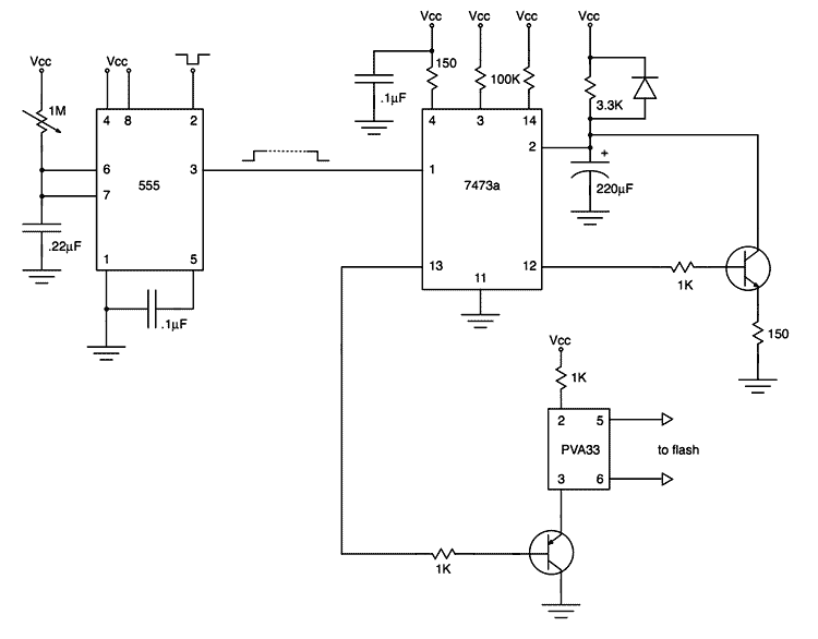
My first project after assembling an electronic design lab was to build a flash trigger that I could use for high-speed photography. I thought it would be useful to share not only the finished product but also the reasoning...
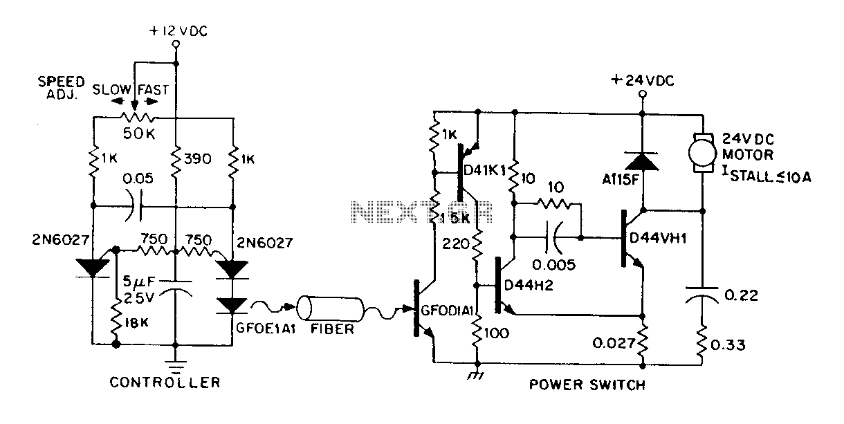
A DC power supply can be controlled through an optical fiber. The circuit includes a small DC motor (1/12 hp) that offers an isolated speed control channel. The control logic operates as an independent module, consuming 300 mW of...
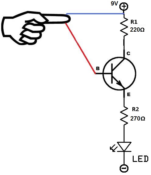
This project utilizes two wires, one red and one blue, which function as touch sensor wires. When a person touches both wires, the circuit closes, allowing current to flow and illuminate the LED. A 9-volt battery or an external...
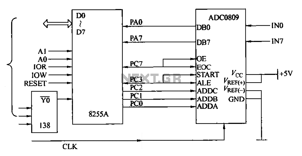
The ADC0809 is an 8-channel analog switch integrated with an 8-bit successive approximation analog-to-digital (A/D) converter. It supports the selection of eight input channels through address latch and encoder channel selection signals ADDA, ADDB, and ADDC. The address latch...
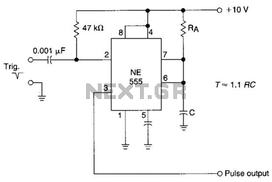
The time constant of RAXC determines the period of the monostable multivibrator. A negative pulse at pin 2 of the 555 starts the cycle. The monostable multivibrator is a circuit configuration that produces a single output pulse in response...
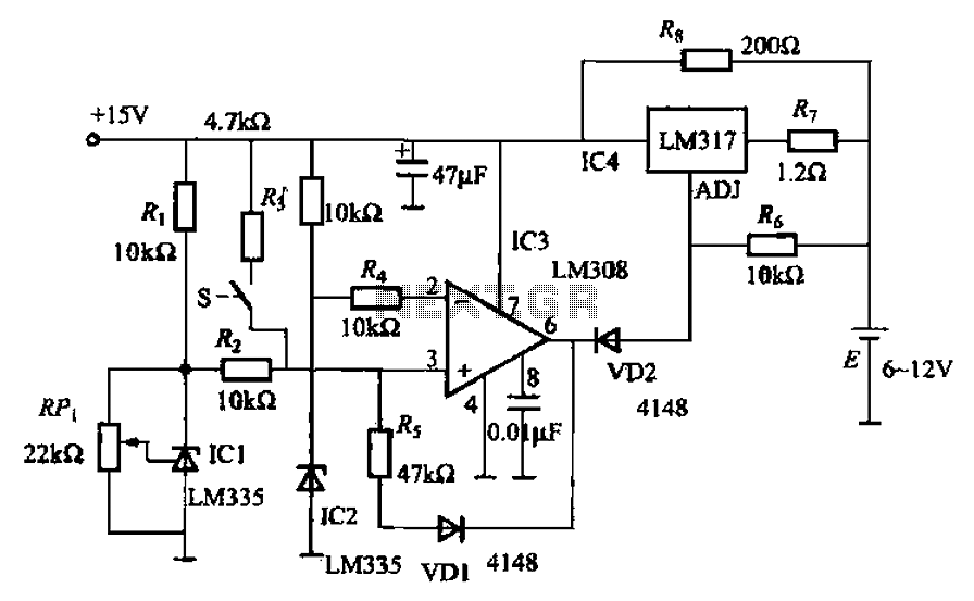
When fast charging a nickel-cadmium battery, the temperature control circuit, as illustrated in the accompanying figure, is designed to monitor the battery temperature to regulate the charging current. The circuit consists of Icl to IC3, which forms the temperature...
Warning: include(partials/cookie-banner.php): Failed to open stream: Permission denied in /var/www/html/nextgr/view-circuit.php on line 713
Warning: include(): Failed opening 'partials/cookie-banner.php' for inclusion (include_path='.:/usr/share/php') in /var/www/html/nextgr/view-circuit.php on line 713