
Short Wave Receiver

The shortwave receiver circuit leverages the Signetics NE602 integrated circuit, which serves as a crucial component in the varactor-tuned front end. This design allows for efficient tuning across a wide frequency range while maintaining simplicity in construction. The NE602 functions as a double-balanced mixer, enabling effective frequency conversion and enhancing the overall performance of the receiver.
In addition to the NE602, the circuit incorporates a ceramic filter that plays a vital role in determining the sensitivity of the receiver. This filter is essential for rejecting unwanted signals and noise, thus improving the clarity of the desired audio output. The two intermediate frequency (IF) stages further amplify the signal, ensuring that the receiver can effectively process weak signals that may be present in the shortwave band.
Automatic Gain Control (AGC) is integrated into the design to maintain a consistent audio output level, regardless of variations in the input signal strength. This feature is particularly important in shortwave reception, where signal strength can fluctuate significantly due to atmospheric conditions and distance from the transmitter.
The audio amplifier stage converts the processed RF signal into audible sound, allowing users to listen to the received transmissions. The overall sensitivity of the circuit is noted to be under 1 µV, indicating its capability to detect weak signals effectively.
Coil data for the circuit is provided for operation within the frequency range of 5 to 16 MHz. The values of capacitors C18, C19, and C23 are frequency-dependent and must be selected based on the specific frequency range in use. Proper selection of these components is critical for optimizing the performance of the receiver and ensuring effective tuning across the desired shortwave frequencies. Using a Signetics NE602 in a varactor-tuned front end, the circuit of a shortwave receiver can be very simple and yet g ive high performance. This circuit also uses a ceramic filter as a sensitivity-deteraiining device, two IF stages, AGC, and an audio amplifier. It has a sensitivity of under 1/iV. The table shows coil data for the frequencies from 5 to 16 MHz. The values Ci8, Ci9, and C23 depend on the frequency range chosen.
Related Circuits
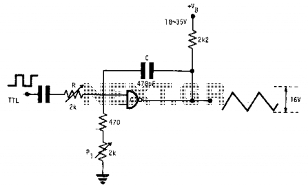
This fixed-frequency triangular waveform generator, driven by a TTL square wave, produces triangular waveforms with a peak-to-peak voltage of typically 16 V at frequencies reaching several MHz. The design utilizes a single AND open collector gate or an open...
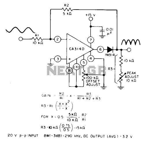
When the equality of two equations is satisfied, the full-wave output of the circuit is symmetrical. The circuit utilizes a CA3140 BiMOS operational amplifier in an inverting gain configuration. The circuit design featuring the CA3140 BiMOS operational amplifier is characterized...

Use #22 Hook-up Wire for Windings. Numbers on coil are connection points to the FAR Circuits PC board. More: Voltages shown are typical values using a 9V battery. C3,C5 are three gang variable capacitor 10-60pF/gang. Many substitutes are possible....
The three-transistor circuit costs less than $10 to build, uses commonly available components, and consumes less than 10 mA from a single 9V battery. By winding coil L1 as shown, the circuit can receive signals in the 5 to...
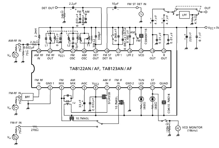
A simple low-power AM/FM radio receiver electronic project can be designed using the TA8122 integrated AM/FM receiver, manufactured by Toshiba Semiconductor. This radio receiver circuit can be utilized for portable radio applications or similar devices. The TA8122 radio receiver...
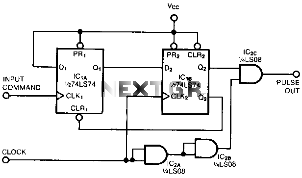
This circuit captures a single positive pulse from a square-wave train. After the rising edge of an input command, the pulse-out signal generates a replica of one positive pulse of the clock signal simultaneously with the next rising edge...