
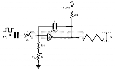
Square wave-to-triangle converter
The triangular waveform generator operates on a principle that combines digital and analog techniques to create a stable and precise output. The input TTL square wave serves as the timing reference, allowing the circuit to produce a triangular waveform at a fixed frequency determined by the timing components. The use of an open collector gate or inverter facilitates fast switching and integration, which is crucial for generating the desired waveform shape.
The integration process involves charging and discharging the capacitor through the resistor R, where the time constants are adjusted to achieve the correct slope of the triangular waveform. The gain provided by the open collector device enhances the output signal, ensuring that it reaches the desired amplitude. The adjustments of R and PI are critical, as they directly influence the frequency response and linearity of the output waveform.
The output characteristics are notably robust, as the amplitude and linearity remain stable across a range of supply voltages (VB). This flexibility allows the circuit to be utilized in various applications without significant recalibration, making it suitable for environments where voltage supply may vary.
In practice, when designing this circuit, careful attention must be paid to the choice of components, especially the capacitor value, which is crucial for maintaining the integrity of the waveform at higher frequencies. As the frequency increases, the capacitor's capacitance must be reduced to maintain the correct timing characteristics, ensuring that the triangular waveform remains sharp and well-defined.
Overall, this fixed-frequency triangular waveform generator is an effective solution for applications requiring precise waveform generation, with the ability to adapt to different operating conditions while maintaining performance integrity.This fixed frequency triangular waveform generator driven by a TTL square wave generates typically 16-V p-p triangles at frequencies up to several MHz. It uses only one AND open collector gate, or one open collector inverter as a fast integrator with gain.
Careful successive adjustments of R and PI are needed. When correct adjustments are reached, output amplitude and linearity are largely independent of the value of VB, from a minimum of 18 V up to 35 V. The value of C shown is for 100 kHz; at higher frequencies, it must be reduced in proportion. 🔗 External reference
Related Circuits
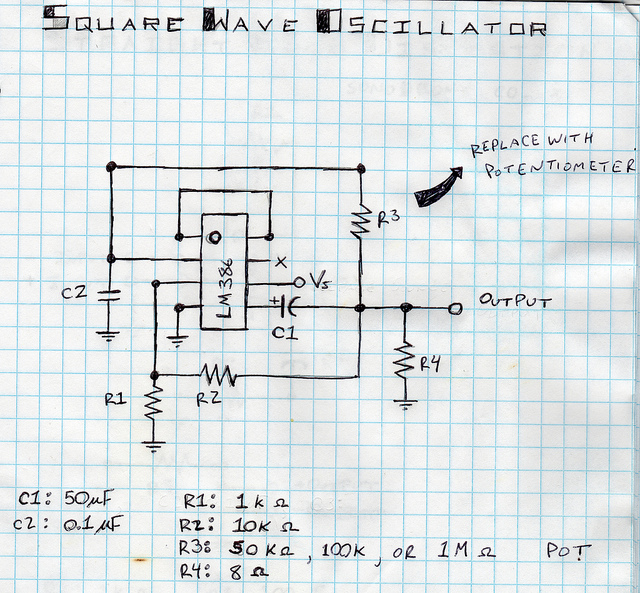
This is a square wave oscillator (digital, similar to 8-bit music). It is based on the LM386 amplifier integrated circuit, which is also the foundation for the mini guitar amplifier. The design includes a simple power switch connected to...
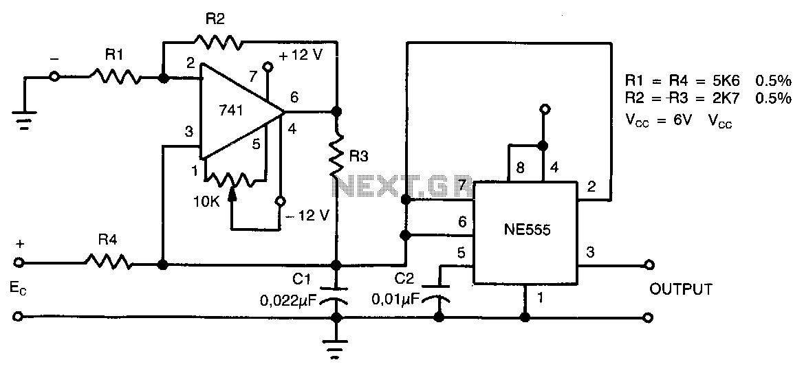
This circuit can accept positive, negative, or differential control voltages. The output frequency is zero when the control voltage is zero. The 741 operational amplifier forms a current source controlled by the voltage Ec to charge the timing capacitor...
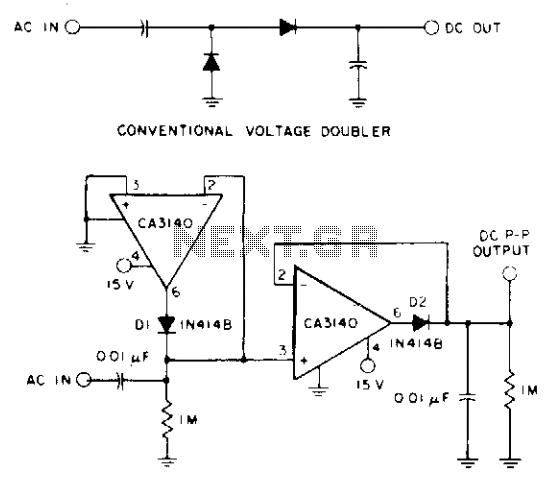
A CA3140 BiMOS operational amplifier, powered by a single positive supply, is employed to convert a traditional voltage doubler utilizing two precision diodes into a precise peak-to-peak AC-to-DC voltage converter. This configuration offers a wide dynamic range and extensive...
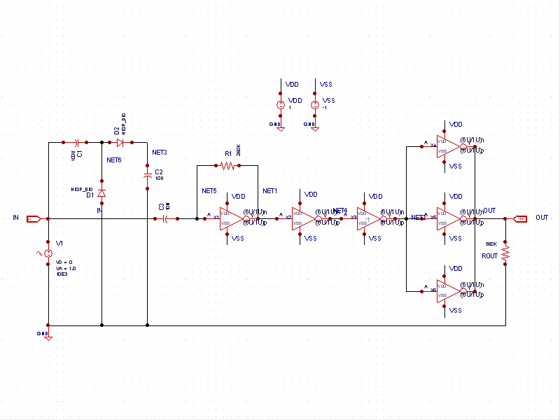
This schematic example demonstrates a sinusoidal voltage input at a frequency of 10 kHz, which is converted to a square wave using an inverter-based circuit. The VDD and VSS rails are connected to +1V and -1V, respectively. The control...
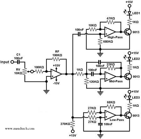
A simple circuit for converting an audio signal (such as one that comes from the output terminals of a CD player). The circuit basically consists of a buffer/amplifier stage and three filter circuits: a high-pass filter, a mid-pass filter,...
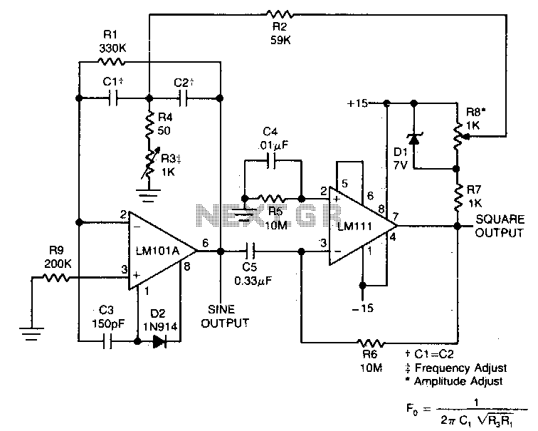
This circuit will provide both a sine and square wave output for frequencies ranging from below 20 Hz to above 20 kHz. The frequency of oscillation can be easily adjusted by changing a single resistor. This circuit is designed to...