
Shortwave fet booster
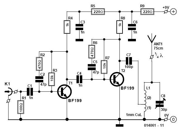
The two-transistor preselector circuit is designed to amplify signals within the frequency range of 3 to 30 MHz, achieving a gain of up to 40 dB. This circuit typically utilizes two transistors, often configured in a common-emitter or common-source arrangement to maximize gain while maintaining stability across the specified frequency range. The choice of a MOSFET for Q1 is particularly advantageous due to its high input impedance and low noise characteristics, which are essential for preserving signal integrity in RF applications.
The design must incorporate appropriate biasing resistors to ensure that the transistors operate in their active regions without distortion. Additionally, coupling capacitors are essential for blocking DC components while allowing AC signals to pass through, thus facilitating the amplification of RF signals.
Careful attention should be paid to the layout of the circuit board, as parasitic capacitances and inductances can significantly affect performance at high frequencies. It is crucial to minimize lead lengths and use short traces to reduce these unwanted effects.
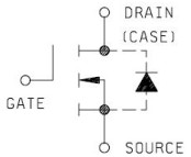
Moreover, the sensitivity of Q1 to static charges necessitates the implementation of ESD (Electrostatic Discharge) protection measures. This can include the use of grounded conductive mats during assembly and the incorporation of protective components, such as diodes, to safeguard the MOSFET from potential damage.
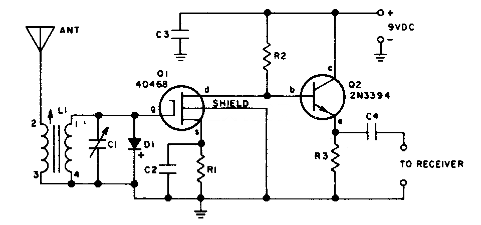
Overall, this two-transistor preselector is an effective solution for enhancing signal levels in the specified frequency range, provided that proper handling and circuit design practices are observed.This two transistor preselector provides up to 40 dB gain from 3 to 30 MHz Ql (MOSFET) is sensitive to static charges and must be handled with care. 🔗 External reference
Related Circuits
This circuit enables the use of a portable VHF FM radio to receive audio from stations that exclusively broadcast on the local cable network. This circuit operates by modulating the audio signals from the local cable network onto a carrier...
MIL-PRF-19500/543; Semiconductor Device, Transistor, Field Effect, N-Channel, Silicon, Repetitive Avalanche Types 2N6764, 2N6764T1, 2N6766, 2N6766T1, 2N6768, 2N6768T1, 2N6770, and 2N6770T1 [TO-204AE; formerly designated as a TO-3] TO-204 Flange mount. [Diamond Base] A package shape which provides a method of...
Two single-ended circuits are connected back to back to provide a differential input. This circuit not only features a differential input but also exhibits high impedance, significantly higher than that of an analog ammeter without this circuit. A schematic...
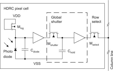
The initial section of this document outlines the high dynamic range CMOS (HDRC) imager, a specialized type of CMOS image sensor characterized by its logarithmic response. The significant capabilities of high dynamic range (HDR) image acquisition are explained through...

This is a design circuit for a low distortion crystal oscillator. The circuit generates a sine wave with low phase noise and distortion, allowing for the use of a crystal with less than 1mV dissipated across it. The crystal...
As readers may know, there are several power amplifier projects, including two that utilize integrated circuit (IC) power amplifiers, commonly referred to as power op-amps. Both of these projects have gained popularity, and this new project is not intended...