
2N2497 Differential FET Voltmeter
The described circuit consists of two single-ended amplifiers arranged in a back-to-back configuration to create a differential input. This arrangement is advantageous for applications requiring high input impedance, which minimizes the loading effect on the signal source. The differential input allows for the rejection of common-mode noise, enhancing the accuracy and reliability of the signal processing.
In this configuration, each single-ended amplifier receives its input from a different source, while the output is taken from the difference between the two signals. This method effectively amplifies the difference between the inputs, which is particularly useful in environments with significant electrical noise or when measuring small signals.
The high impedance characteristic of this circuit is achieved through the use of operational amplifiers (op-amps) or specialized high-impedance buffer circuits. The op-amps are configured in such a way that they present a high resistance to the input signal, allowing for minimal current draw from the signal source. This is critical in preserving the integrity of the signal, especially in sensitive applications such as sensor interfacing or data acquisition systems.
The schematic diagram accompanying the description illustrates the connections and components used in the circuit. It typically includes the op-amps, resistors, and any necessary capacitors for stability and filtering. Proper selection of these components is essential to achieve the desired performance characteristics, including bandwidth, gain, and noise performance.
In conclusion, the back-to-back single-ended circuit configuration provides an effective solution for applications requiring differential input with high impedance, ensuring accurate signal processing and noise rejection.Below is two single ended circuits which connected back to back give differential input. This circuit is not only has differential input feature, but also high impedance, much higher compared with the analog ammeter without this circuit. Here is the schematic diagram of the circuit: We aim to transmit more information by carrying articles.
Please send us an E-mail to wanghuali@hqew. net within 15 days if we are involved in the problems of article content, copyright or other problems. We will delete it soon. 🔗 External reference
Related Circuits
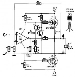
This audio power amplifier employs two complementary MOSFETs (IRF9520 and IRF520) to provide up to 20W output into an 8-ohm speaker. A TL071 operational amplifier functions as the input amplifier. The MOSFETs require heatsinking with a thermal resistance of...
Can be directly connected to CD players, tuners and tape recorders. Simply add a 10K Log potentiometer (dual gang for stereo) and a switch to cope with the various sources you need. Q6 & Q7 must have a small...
This circuit includes a 220µF capacitor and two diodes designed to slow down the switch-on process, thereby minimizing the output thump that occurs as the output capacitor charges through the speaker. While this feature is not essential and may...
This is a simple high-gain JFET audio amplifier circuit. This circuit requires very low power but provides a high-gain amplification function. It is also referred to as JFET. The JFET (Junction Field Effect Transistor) audio amplifier circuit is designed to...
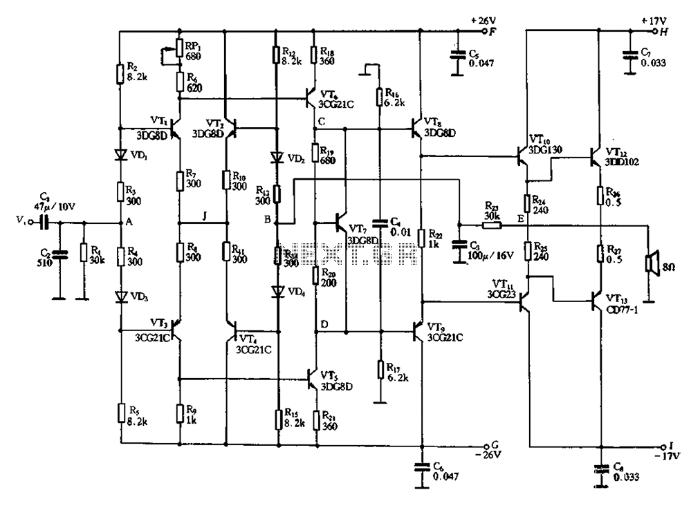
Almost all DC amplifier circuits are utilized as the input stage of differential circuits. Many complementary symmetry circuits also employ a double differential complementary sub-circuit along with a constant current source for the input stage. The constant current source...
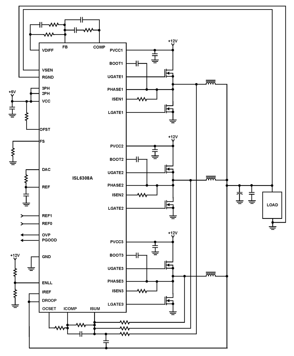
The ISL6308A is a three-phase PWM control integrated circuit (IC) equipped with built-in MOSFET drivers. It delivers precise voltage regulation suitable for various applications, including high current low voltage point-of-load converters, embedded systems, and other general low voltage medium...
Warning: include(partials/cookie-banner.php): Failed to open stream: Permission denied in /var/www/html/nextgr/view-circuit.php on line 713
Warning: include(): Failed opening 'partials/cookie-banner.php' for inclusion (include_path='.:/usr/share/php') in /var/www/html/nextgr/view-circuit.php on line 713