
signal tracer using lm386 amplifier chip
The circuit design leverages the LM386, a low-voltage audio power amplifier capable of delivering significant output power while maintaining low distortion. The LM386 operates with a supply voltage ranging from 4 to 12 volts, making it versatile for different applications. Its internal gain is set at 200, but this can be adjusted by adding external resistors and capacitors.
The inclusion of a transistor at the input stage serves multiple purposes. It acts as a buffer, isolating the input signal source from the LM386, which can enhance the overall performance by preventing loading effects that might distort the signal. Additionally, the transistor can provide extra gain, improving the circuit's sensitivity and allowing it to amplify weaker signals effectively.
The circuit typically consists of a few additional passive components, such as resistors and capacitors, which stabilize the amplifier and filter unwanted noise. A bypass capacitor may be included to smooth out power supply fluctuations, ensuring clean operation. The output stage of the LM386 can be connected directly to speakers or other audio outputs, depending on the application.
Overall, this circuit is an efficient solution for amplifying audio signals in various consumer electronics, providing a reliable method for enhancing sound quality in devices like televisions, radios, and car audio systems. Its simplicity and effectiveness make it a popular choice for audio amplification tasks.The main part of this circuit is the LM386 amplifier chip. It also uses a transistor input to buffer the input signal and provide extra gain for the LM386. The little unit has helped me out on numerous occasions when trouble shooting any amplifier circuit like a stereo receiver, tv / vcr audio section, radios, cd players and car stereos. 🔗 External reference
Related Circuits
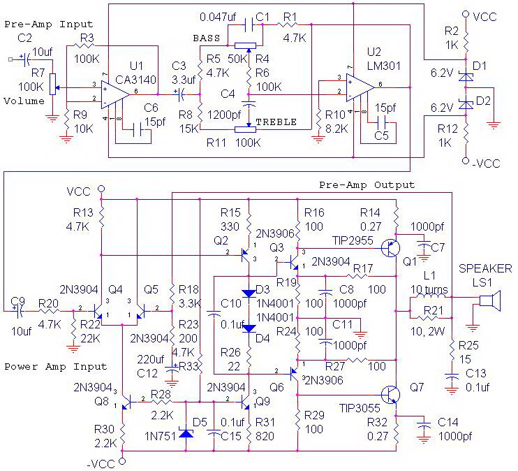
The circuit power amplifier depicted is a schematic design for a power amplifier with an output power of 70 watts, operating in Class AB mode. This power amplifier circuit is equipped with a tone control circuit. The 70-watt power...
Here is a circuit of a remote control unit which makes use of the radio frequency signals to control various electrical appliances. This remote control unit has 4 channels which can be easily extended to 12. This circuit differs...
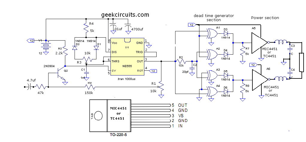
This document presents an improvised circuit model designed to eliminate unwanted DC offset voltage from the output, which affects previously discussed circuits. All prior circuits were intended as low-power Class D amplifier sources suitable for driving headphones through a...
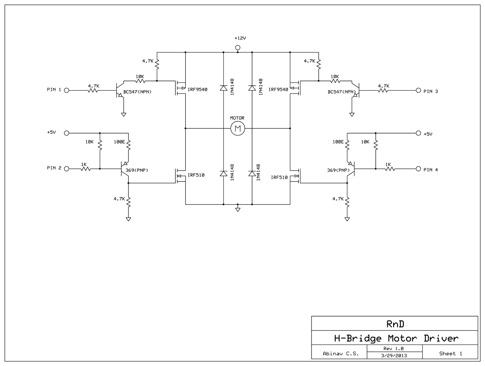
This post discusses the construction of an H-Bridge Motor Driver circuit using simple MOSFETs and transistors. The primary feature of this H-Bridge is its ability to drive a motor in both directions. An H-Bridge is a circuit that allows...
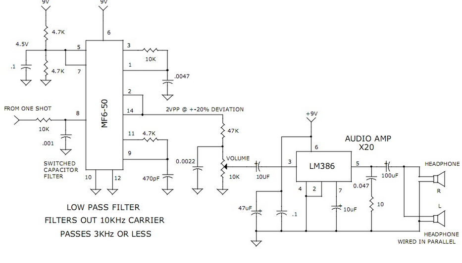
This circuit utilizes a switched capacitor filter integrated circuit (IC) from National Semiconductor to filter signals with frequencies exceeding 3 kHz, which are not required for voice audio. The circuit design incorporates a switched capacitor filter IC, which is a...
This circuit utilizes the SIEMENS and UAA180 rectification measurement circuits for accurate signal processing, centered around the TL072 integrated circuit (IC2B). Calibration occurs in 3dB increments, ensuring a high level of precision for measuring incoming acoustic signals. The LEDs...
Warning: include(partials/cookie-banner.php): Failed to open stream: Permission denied in /var/www/html/nextgr/view-circuit.php on line 713
Warning: include(): Failed opening 'partials/cookie-banner.php' for inclusion (include_path='.:/usr/share/php') in /var/www/html/nextgr/view-circuit.php on line 713