
Remote Control using DTMF
The remote control circuit described operates using radio frequency signals to manage electrical appliances, offering a significant advantage over traditional infrared systems, which are limited to line-of-sight operation. The core of this system is the DTMF (Dual-Tone Multi-Frequency) signaling method, which is commonly found in telephone dialers. The transmitter employs the UM91214B integrated circuit to generate DTMF tones, which are then frequency modulated and transmitted via an FM transmitter circuit.
The transmitter circuit is powered by a 9V supply that is stepped down to 3V using a zener diode regulator, ensuring the UM91214B operates within its specified voltage range. A quartz crystal oscillator provides the necessary timing for the DTMF generation, with a frequency of 3.58 MHz. The circuit utilizes a series of push-to-on switches that, when pressed, generate corresponding DTMF tones while simultaneously powering the transmitter, thus conserving battery life.
On the receiver side, an FM receiver module captures the transmitted DTMF signals. These signals are decoded by the KT3170 DTMF-to-BCD converter, which outputs binary-coded decimal signals corresponding to the pressed digits. The outputs from this IC are fed into toggle flip-flops constructed from CD4013B ICs, allowing for the control of multiple electrical appliances. Each flip-flop can toggle the state of a relay, which is connected to the appliance being controlled.
For scalability, the system can be expanded to control up to 12 appliances by utilizing additional circuitry, including a 4-to-16 line demultiplexer (IC 74154) and extra flip-flops. This flexibility allows the user to customize the remote control system according to their specific needs, making it a versatile solution for wireless appliance management. The entire setup is designed to be housed in a metallic enclosure to minimize interference and ensure stable operation.Here is a circuit of a remote control unit which makes use of the radio frequency signals to control various electrical appliances. This remote control unit has 4 channels which can be easily extended to 12. This circuit differs from similar circuits in view of its simplicity and a totally different concept of generating the control signals.
Usually remote control circuits make use of infrared light to transmit control signals. Their use is thus limited to a very confined area and line-of-sight. However, this circuit makes use of radio frequency to transmit the control signals and hence it can be used for control from almost anywhere in the house. Here we make use of DTMF (dual-tone multi frequency) signals (used in telephones to dial the digits) as the control codes.
The DTMF tones are used for frequency modulation of the carrier. At the receiver unit, these frequency modulated signals are intercepted to obtain DTMF tones at the speaker terminals. This DTMF signal is connected to a DTMF-to-BCD converter whose BCD output is used to switch-on and switch-off various electrical applicances (4 in this case).
The remote control transmitter consists of DTMF generator and an FM transmitter circuit. For generating the DTMF frequencies, a dedicated IC UM91214B (which is used as a dialler IC in telephone instruments) is used here. This IC requires 3 volts for its operation. This is provided by a simple zener diode voltage regulator which converts 9 volts into 3 volts for use by this IC.
For its time base, it requires a quartz crystal of 3.58 MHz which is easily available from electronic component shops. Pins 1 and 2 are used as chip select and DTMF mode select pins respectively. When the row and column pins (12 and 15) are shorted to each other, DTMF tones corresponding to digit 1 are output from its pin 7.
Similarly, pins 13, 16 and 17 are additionally required to dial digits 2, 4 and 8. Rest of the pins of this IC may be left as they are. The output of IC1 is given to the input of this transmitter circuit which effectively frequency modulates the carrier and transmits it in the air. The carrier frequency is determined by coil L1 and trimmer capacitor VC1 (which may be adjusted for around 100MHz operation).
An antenna of 10 to 15 cms (4 to 6 inches) length will be sufficient to provide adequate range. The antenna is also necessary because the transmitter unit has to be housed in a metallic cabinet to protect the frequency drift caused due to stray EM fields. Four key switches (DPST push-to-on spring loaded) are required to transmit the desired DTMF tones. The switches when pressed generate the specific tone pairs as well as provide power to the transmitter circuit simultaneously.
This way when the transmitter unit is not in use it consumes no power at all and the battery lasts much longer. The receiver unit consists of an FM receiver (these days simple and inexpensive FM kits are readily available in the market which work exceptionally well), a DTMF-to-BCD converter and a flip-flop toggling latch section.
The frequency modulated DTMF signals are received by the FM receiver and the output (DTMF tones) are fed to the dedicated IC KT3170 which is a DTMF-to-BCD converter. This IC when fed with the DTMF tones gives corresponding BCD output; for example, when digit 1 is pressed, the output is 0001 and when digit 4 is pressed the output is 0100.
This IC also requires a 3.58MHz crystal for its operation. The tone input is connected to its pin 2 and the BCD outputs are taken from pins 11 to 14 respectively. These outputs are fed to 4 individual D flip-flop latches which have been converted into toggle flip-flops built around two CD4013B ICs.
Whenever a digit is pressed, the receiver decodes it and gives a clock pulse which is used to toggle the corresponding flip-flop to the alternate state. The flip-flop output is used to drive a relay which in turn can latch or unlatch any electrical appliance.
We can upgrade the circuit to control as many as 12 channels since IC UM91214B can generates 12 DTMF tones. For this purpose some modification has to be done in receiver unit and also in between IC2 and toggle flip-flop section in the receiver.
A 4-to-16 lines demultiplexer (IC 74154) has to be used and the number of toggle flip-flops have also to be increased to 12 from the existing 4. 🔗 External reference
Related Circuits
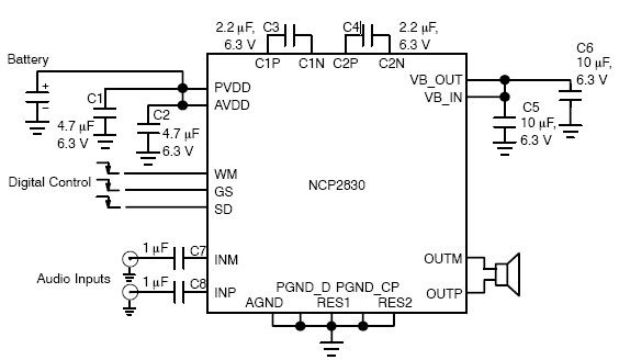
The NCP2830 audio power amplifier features high-quality audio performance with a total harmonic distortion plus noise (THD+N) of 0.04%. It offers low noise with a signal-to-noise ratio (SNR) of up to 100 dB and optimizes overall system efficiency, achieving...
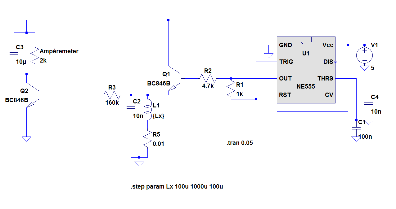
The objective of the project is to construct a simple, low-cost inductance meter. The primary components of the project include an IC 555, a transistor, a resistor, and a capacitor. The inductance meter designed in this project utilizes the IC...
The following circuit illustrates the circuit diagram of a motor control unit. This circuit is based on the LM317 integrated circuit (IC). Features include diodes that protect the regulator. The motor control unit circuit utilizes the LM317 voltage regulator to...
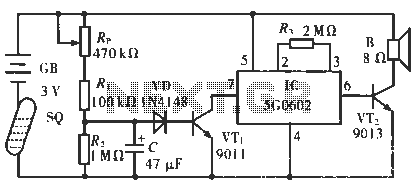
The circuit operates in such a way that when the patient is typically in an upright position, the SQ mercury switch is turned off, resulting in the alarm circuit being inactive. When the patient lies down, the SQ switch...
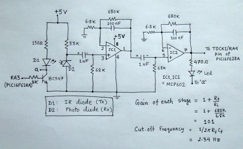
The reflected infrared (IR) signal detected by the photodiode is sent to a signal conditioning circuit, which filters out unwanted signals and amplifies the desired output. The circuit begins with a photodiode that captures the reflected IR signals. The photodiode...

A general-purpose preamplifier/mixer accepts up to four inputs, has a gain of 1600, and provides bass and treble controls that can be varied ± 10 dB at 100 Hz and 10 kHz respectively. More: IC1 and IC2 = LM301A. This...
Warning: include(partials/cookie-banner.php): Failed to open stream: Permission denied in /var/www/html/nextgr/view-circuit.php on line 713
Warning: include(): Failed opening 'partials/cookie-banner.php' for inclusion (include_path='.:/usr/share/php') in /var/www/html/nextgr/view-circuit.php on line 713