
Simple 12V battery circuit with diagram
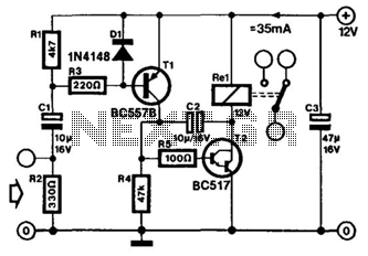
The 12V battery charging circuit is designed to charge lead-acid batteries using a trickle charging method, ensuring a safe and efficient charging process. The circuit typically includes a transformer, a rectifier, a filter capacitor, and a voltage regulator to maintain the appropriate charging voltage.
The transformer steps down the AC voltage from the mains supply to a lower AC voltage suitable for charging the battery. The rectifier, often composed of diodes, converts the AC voltage to pulsating DC voltage. A common configuration is a full-wave rectifier, which utilizes four diodes arranged in a bridge configuration to improve efficiency.
After rectification, the pulsating DC voltage is smoothed using a filter capacitor, which reduces voltage ripple and provides a more stable DC output. This output is then fed into a voltage regulator, which ensures that the voltage remains at a safe level for charging the lead-acid battery, typically around 13.8V to 14.4V, depending on the specific battery chemistry and state of charge.
Additional components may include a current-limiting resistor or a charge controller to prevent overcharging, which can lead to battery damage. The trickle charger operates by supplying a low and constant charging current, which is ideal for maintaining battery health over extended periods without causing overheating or excessive gassing.
This circuit can be implemented using discrete components or integrated circuits designed for battery management. Proper heat dissipation methods, such as heat sinks for the rectifier diodes, should be considered to ensure reliable operation during charging. Overall, this 12V battery charging circuit is an effective solution for maintaining lead-acid batteries in various applications.A 12V battery full charging circuit with simple diagram for rectifier is given.The lead acid trickle charger circuit is explained with a rectifier.. 🔗 External reference
Related Circuits
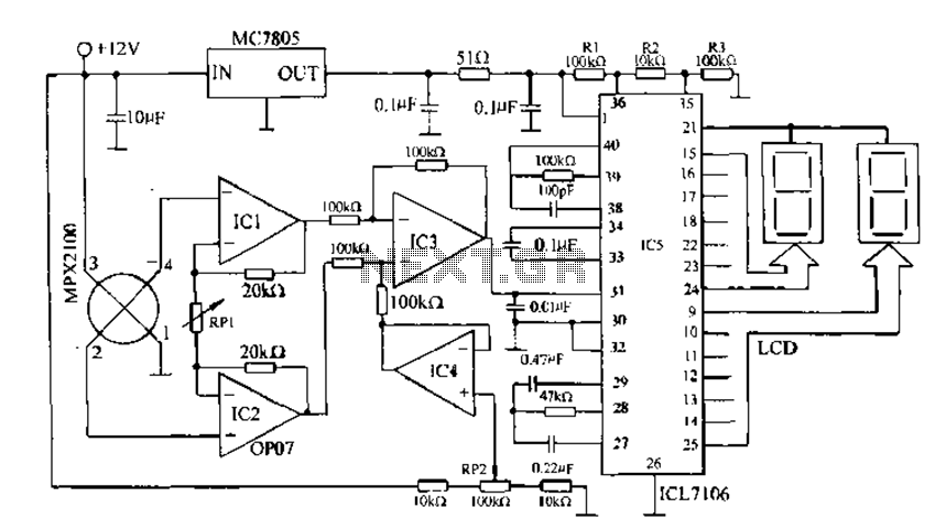
Digital pressure measuring circuit using AD7710/7715/7730 multifunction digital sensor signal conditioning ICs. These ICs integrate a digital interface with the control port, a clock generator, a digital filter, amplitude modulation, a programmable gain amplifier, an A/D converter, and other...
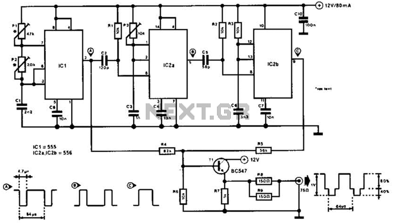
The video master comprises a series of converters that allocate all video sources to unused UHF channels. These channels are then combined with standard TV channels, whether terrestrial or cable, into a single cable. This single cable can subsequently...
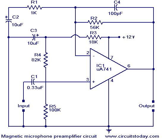
A preamplifier for magnetic pickups of record players is presented. The uA 741 is utilized as an AC-coupled non-inverting amplifier operating on a single supply. The amplifier gain is determined by the feedback components, where C2 manages the low-frequency...
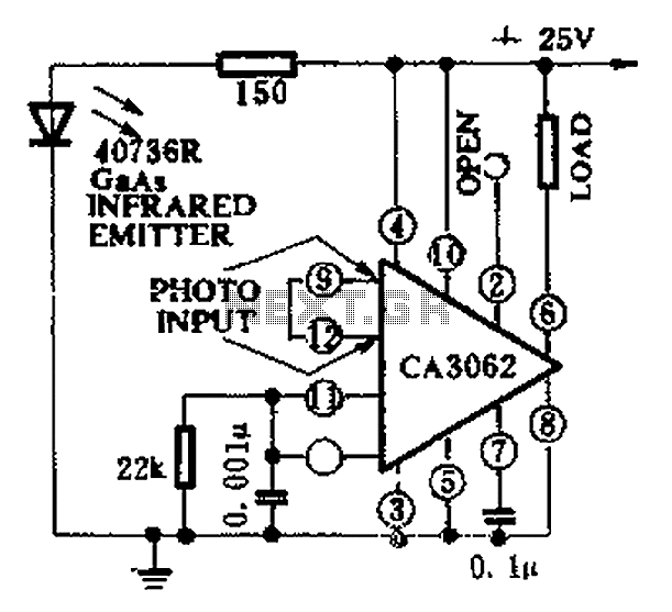
CA3062 is a combined photodetector and power amplifier that responds to the optical signal generated by the on/off output. The integrated circuit's transistor output saturation should be either on or off to prevent temperature rise in the silicon. When...
The following circuit diagram depicts a 100 Watt audio power amplifier, constructed using the LM3886 power amplifier chip. A single LM3886 IC can amplify audio power output up to 68W. In this circuit, two LM3886 chips are configured in...
A VOX is a voice-operated switch that is often used as a substitute for the press-to-talk switch on a microphone. This VOX can be connected to almost any audio equipment that has a socket for an external loudspeaker. The...
Warning: include(partials/cookie-banner.php): Failed to open stream: Permission denied in /var/www/html/nextgr/view-circuit.php on line 713
Warning: include(): Failed opening 'partials/cookie-banner.php' for inclusion (include_path='.:/usr/share/php') in /var/www/html/nextgr/view-circuit.php on line 713