
Magnetic pickup pre-amplifier circuit
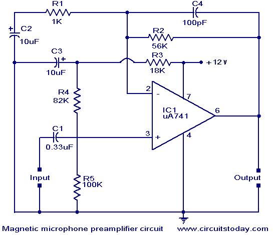
The described preamplifier circuit is essential for enhancing the signal from magnetic pickups found in record players, which typically produce low-level outputs. The uA 741 operational amplifier is a widely used component due to its versatility and performance in audio applications. As an AC-coupled amplifier, it allows for the amplification of AC signals while blocking any DC offset that may interfere with the audio signal.
The selection of feedback components is crucial for tailoring the frequency response of the amplifier. Capacitor C2 plays a significant role in defining the low-frequency cutoff point, ensuring that unwanted low-frequency noise is attenuated, which is particularly important for preserving audio fidelity. Capacitor C4, on the other hand, acts to limit high-frequency gain, preventing distortion that could arise from excessive amplification of high-frequency signals, which are often present in the output of magnetic pickups.
The voltage divider formed by resistors R3, R4, and R5 is designed to set the bias point of the non-inverting input. By establishing a bias voltage of approximately half the supply voltage, the circuit ensures that the output signal can swing equally above and below this midpoint, maximizing the dynamic range of the amplifier output.
To further enhance the performance of the preamplifier, R5 and C3 work together to create a low-pass filter that mitigates power supply noise and hum. This is particularly beneficial in environments where multiple circuits may be powered from the same supply, as it helps to isolate the preamplifier from potential interference caused by other components.
Overall, the circuit design effectively addresses the challenges associated with amplifying low-level audio signals from magnetic pickups while ensuring high fidelity and minimal noise interference. This makes it an integral component in high-quality audio playback systems.A preamplifier for magnetic pickups of record players is shown here. The uA 741 is used as an AC coupled non-inverting amplifier operating on a single supply. The amplifier gain is decided by the feedback components in which C2 controls the low frequency roll-off characteristics while C4 reduces the gain at high frequency end to compensate for the p ickup characteristics. R3, R4 and R5 form a voltage divider to give a bias of about half the supply voltage to the non-inverting of uA741. The output at pin6 therefore stands at half the supply voltage. R5 and C3 form a supply line filter to reduce the hum level ans also to eliminate growling in case the preamplifier circuit is operated on a common supply with other circuits.
🔗 External reference
Related Circuits
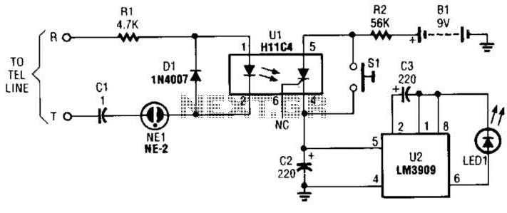
The circuit is constructed using a pair of low-cost integrated circuits (ICs): an H11C4 optoisolator/coupler with a silicon-controlled rectifier (SCR) output (U1) and an LM3909 LED flasher (U2). It connects to the phone line in the same way as...
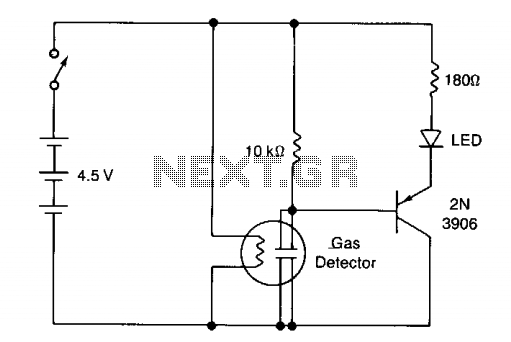
The circuit illustrates a basic yes/no gas detector. It utilizes three 1.5-V D cells as the power source, with SI functioning as an on/off switch. The heater is powered directly from the battery, while the electrodes are connected in...
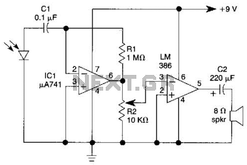
This light-wave receiver comprises a 741 operational amplifier functioning as a preamplifier and an LM386 operational amplifier serving as a power amplifier. The gain control is managed by a potentiometer labeled R2. Various types of detectors can be utilized...
LEDs lining the headliner will fade in when the door is opened and fade out when the door is closed. The necessary components include a circuit to utilize 12V power from the vehicle to illuminate 15 LEDs and control...
The concept for this crystal tester circuit originated from the necessity to evaluate a large quantity of oscillator crystals that were not in use within a hobby box. Testing each crystal individually without the proper equipment would have been...

The circuit illustrated below represents a simple thermometer circuit based on the LM335 temperature sensor. This circuit comprises two main components: the LM335 sensor and its adjustment circuitry. The output from the LM335 generates a voltage of 10 millivolts...