
Color Sensor Circuit With CD4073 IC
The color sensor circuit typically employs a light-sensitive component, such as a photodiode or phototransistor, to detect and differentiate colors based on the wavelength of light. The circuit may include an RGB (Red, Green, Blue) sensor, which is capable of measuring the intensity of each primary color in the light spectrum.
In a standard configuration, the RGB sensor outputs three analog voltage levels corresponding to the intensity of red, green, and blue light. These outputs are then fed into an analog-to-digital converter (ADC), which translates the analog signals into digital values for further processing.
The microcontroller, often the central processing unit of the circuit, interprets these digital values to determine the color of the detected object. It can be programmed to respond to specific colors, triggering actions such as lighting up an LED of the corresponding color, activating a motor, or sending data to a display.
Power supply considerations are crucial in this circuit. A regulated voltage source is typically required to ensure stable operation of the sensor and the microcontroller. Additionally, bypass capacitors may be included near the power pins of the components to filter out noise and ensure reliable performance.
Overall, this color sensor circuit integrates optical sensing with digital processing, allowing for versatile applications in robotics, automation, and interactive systems.This circuit shows a color sensor circuit diagram. The circuit is based on the fundamentals of optics and digital electronics. This circuit will .. 🔗 External reference
Related Circuits
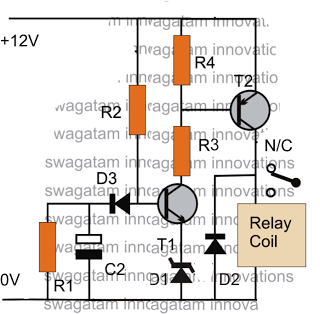
The post discusses a simple delay ON circuit that enables a connected load at the output to be activated with a predetermined delay after the power switch is turned ON. This circuit can be utilized in various applications that...
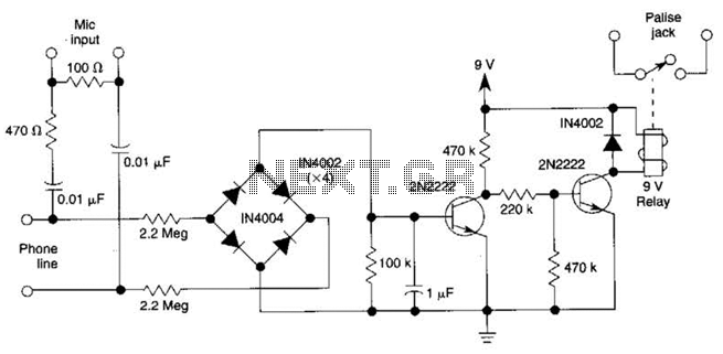
The DC voltage on a telephone line typically ranges from 45 to 50 V when on-hook and drops to around 6 V when off-hook. This circuit utilizes the voltage drop to activate a relay, which in turn controls a...
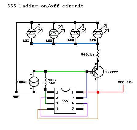
A circuit was constructed based on an LED beating heart frame instructable, but it is not functioning as expected. There is also mention of a built LED sequencer. The LED beating heart circuit typically involves a microcontroller, such as an...
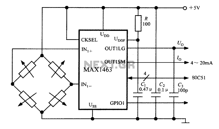
The system consists of a MAX1463 precision pressure detection circuit block diagram. The output voltage from the bridge pressure sensor is connected to the MAX1463 inputs IN1+ and IN1-. Controlled by a CPU, the pressure signal undergoes nonlinear calibration...
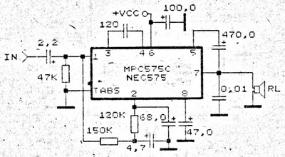
An amplifier circuit is particularly well-suited for use in confined spaces, such as within vehicles. It requires a voltage supply ranging from 9 Volts to a maximum of 17 Volts. This amplifier circuit utilizes the IC MPC575C, which is...
While developing an infrared (IR) extender circuit, a method was needed to measure the relative intensities of different infrared light sources. This circuit utilizes an SFH2030 photodiode as the infrared sensor. A CA3140 MOSFET operational amplifier is employed in...