
Simple AM Transmitter circuit
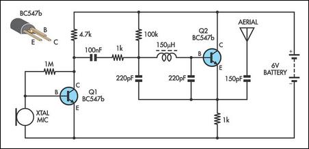
This AM transmitter circuit utilizes a straightforward design approach that enhances accessibility for builders. The use of a single winding inductor eliminates the complexity typically associated with tapped inductors, making it an ideal choice for hobbyists and beginners. The RF choke, readily available in the market, simplifies the assembly process as no winding is required, thus reducing assembly time and potential errors.
The decision to forgo a variable tuning capacitor in favor of fixed 220pF capacitors is a strategic choice aimed at compactness. By employing fixed capacitors, the circuit achieves a smaller footprint, which is beneficial for portable applications. The tuning mechanism relies on adjusting capacitance values, allowing for frequency modulation without the need for bulky components. This flexibility in tuning is crucial for achieving the desired transmission frequency while maintaining the compact nature of the circuit.
The biasing of transistor Q1 with a 1MΩ resistor is significant for ensuring a high input impedance. This characteristic is particularly advantageous when interfacing with low-impedance devices such as crystal earpieces. The use of a crystal earpiece as a microphone not only reduces costs but also simplifies the overall design, making it accessible for those with limited resources.
Overall, this AM transmitter circuit exemplifies an efficient and economical approach to AM transmission, combining simplicity and functionality in a compact design suitable for various applications.There are not many AM transmitters that are easier to build than this one because the inductor is not tapped and has a single winding. There is no need to wind the inductor as it is a readily available RF choke (eg, Jaycar Cat LF-1536).
To make the circuit as small as possible, the conventional tuning capacitor has been dispensed with and fixed 220pF capacitors used instead. To tune it to a particular frequency, reduce one or both of the 220pF capacitors to raise the frequency or add capacitance in parallel to lower the frequency.
Q1 is biased with a 1MO resistor to give a high input impedance and this allows the use of a crystal ear piece as a low cost microphone.. 🔗 External reference
Related Circuits
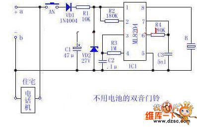
Utilize the 48V (60V) DC feedback electric current supplied by the phone feedback line as the operational energy source for the electronic doorbell, which is highly economical and practical. This document introduces a two-tone doorbell circuit that operates without...

This circuit creates an impressive display of magnetism by suspending a small metal object in mid-air. Utilizing an electromagnet, a photo sensor, and a closed-loop control system, lightweight metal objects can be levitated just beneath the magnet, enclosed in...
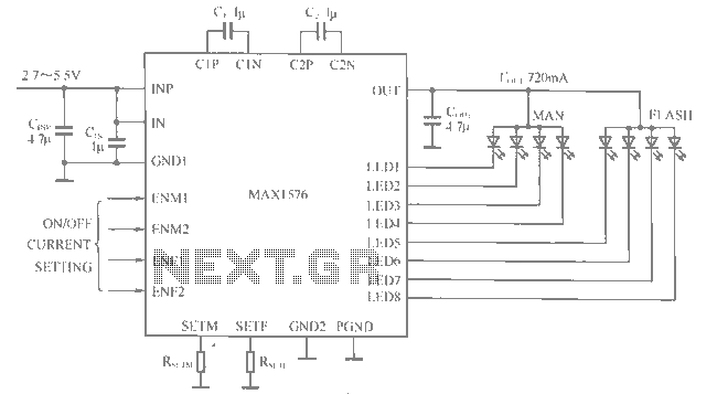
The MAX1516 charge pump drives up to 8 white LEDs with constant current regulation to achieve uniform light intensity, capable of delivering up to 30mA per LED for backlighting. The flash group LEDs (LED5 to LED8) are individually controlled,...
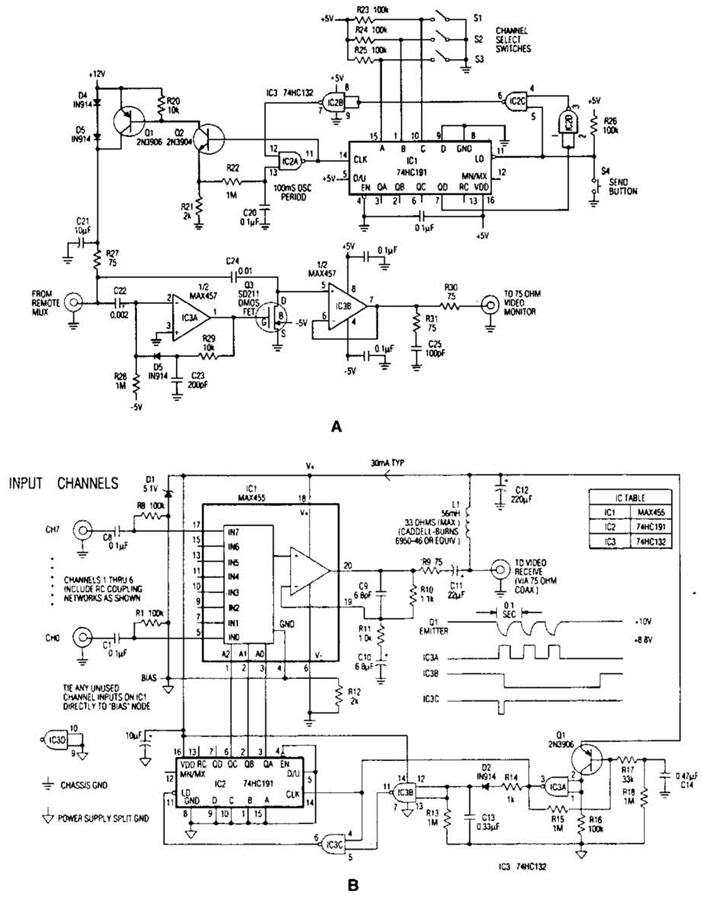
In the video system shown in Figs. A and R, a single coaxial cable transmits power to a remote location, selects one of eight video channels, and returns the chosen signal. This system can select from multiple remote surveillance...
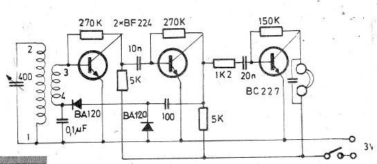
Oscillating circuits (coils) are constructed on a ferrite bar. For long wave reception, winding "1-2" consists of 135 turns, while winding "3-4" consists of 20 turns. For medium wave reception, winding "1-2" has 75 turns, and winding "3-4" has...
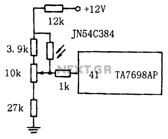
The circuit for automatic brightness adjustment in a television utilizes a photosensitive resistor and a contrast potentiometer connected to an intermediate stage. The photosensitive resistor varies its resistance based on light intensity, causing changes in the potential at the...
Warning: include(partials/cookie-banner.php): Failed to open stream: Permission denied in /var/www/html/nextgr/view-circuit.php on line 713
Warning: include(): Failed opening 'partials/cookie-banner.php' for inclusion (include_path='.:/usr/share/php') in /var/www/html/nextgr/view-circuit.php on line 713