
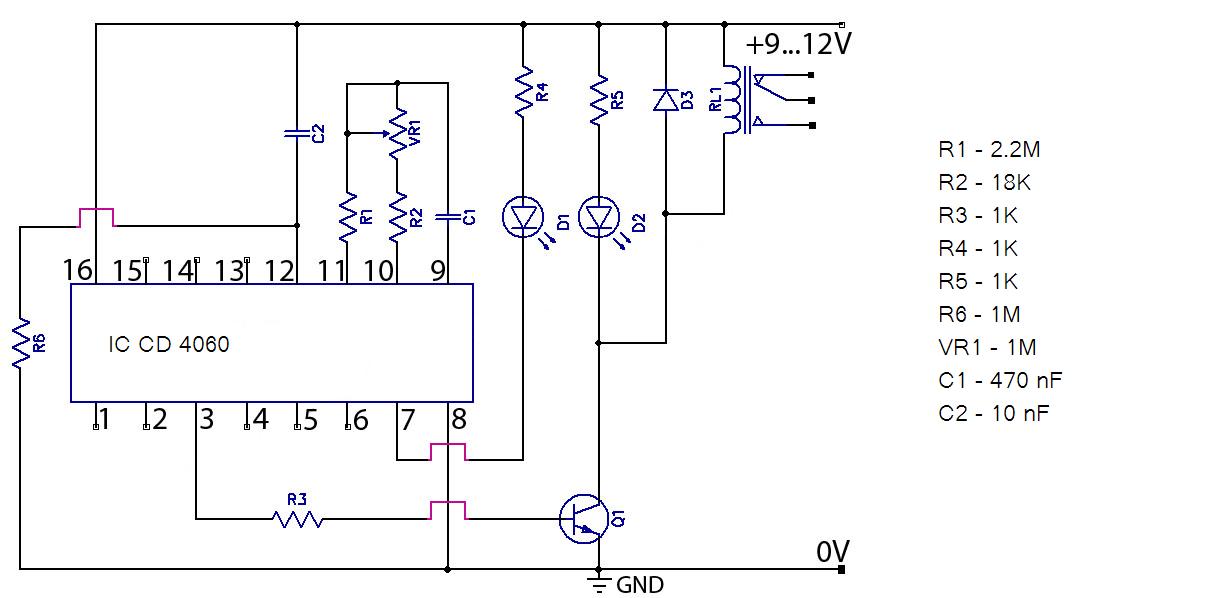
electromagnetic levitator circuit

The circuit design is centered around the principles of electromagnetic levitation, where the balance of forces is crucial for stable operation. The photo sensor continuously monitors the position of the levitated object and sends feedback to the control circuit. This feedback loop is essential for adjusting the electromagnet's current, ensuring that the magnetic field strength is sufficient to counteract gravitational forces acting on the object.
The PCB layout should include traces for power distribution, signal paths, and ground connections, designed to minimize inductance and resistance. Component placement should facilitate efficient signal flow and thermal management. The use of decoupling capacitors near the power supply pins of the ICs will help stabilize voltage levels and reduce noise.
The enclosure design should consider both aesthetics and functionality, providing a stable base for the circuit and electromagnet while allowing for visibility of the levitating object. Adequate ventilation may be necessary to dissipate heat generated by the electromagnet during operation. Additionally, the assembly should include provisions for securing the PCB and ensuring that all components are adequately insulated to prevent short circuits.
In summary, this project not only demonstrates the fascinating effects of magnetism but also provides a practical application of control systems, circuit design, and assembly techniques, making it an engaging endeavor for electronics enthusiasts.This circuit creates a stunning display of the "magic" of magnetism by suspending a small metal object in mid air. Using an electromagnet, photo sensor and closed loop control, small and light metal objects can be floated just underneath the magnet, enclosed in a decorative arch.
"No strings" are easily demonstrated by the ability to pick the meta l object out of the air and place it back under the magnet at will. With the object floating about 1/4" under the magnet (exact distance will depend on the weight of the object), an LED and photo transistor arrangement let a feedback circuit know it`s position. The circuit controls current to an electromagnet to maintain an equilibrium between the force of the magnet and gravity.
Thus, the object floats. Impart a bit of a spin to the object and momentum will carry it for quite a long time as the only friction working against it is between the object and the air. This project is built in two sections; the circuit and then the enclosure/base. Assembly of the circuit should take place on a printed circuit board to minimize the chance of oscillation and to keep the assembly need and compact.
A printed circuit board pattern is provided below. Before using it as a template for your board (using either a photographic or laser process) it is important to check its dimensions when printed. Make a test print on regular paper and then measure the result, comparing it to the measurement shown on the board pattern.
If they don`t match, you will need to adjust your printing settings or scale the pattern in the photo editing software of your choice. While a tiny amount of variance will not make much of a difference, about 1MM is enough to make fitting ICs very difficult.
Once you are satisfied your pattern is correct, etch the board using the method of your choice and then drill out component lead holes. Assemble the parts onto the board using the parts placement diagram shown below. Make sure to check the position of all polarized parts against the schematic before they are soldered into the board.
ICs, diodes, transistors, electrolytic capacitors and LEDs must be placed properly or they will not function and may be damaged. As the board will be mounted into a case, some components are mounted off board with wire leads connecting them to the PCB.
D1, D3, Q1, R9, L1 and S1 should be connected to the board via wire leads. S1, R9 and D3 should be on leads about 6" to allow mounting on the front of the case. Q1 and D1 will require longer leads (about 8-10") as they will be mounted on the bracket supporting the electromagnet. L1, the magnet, needs enough lead length to get it to the top of that bracket so use between 12" and 14" of wire.
L1 is the electromagnet coil assembly from a Potter & Brumfield KUP11D15-6VDC relay. Pull the relay casing off and then remove the coil assembly by snapping its bracket from the plastic bottom. Be careful not to damage the coil windings or the fragile leads connecting the coil to the pins. The KUP11D15 is available from many online suppliers and quite likely through your local electronics store.
It was commonly used in HVAC so if you are having trouble locating it through an electronics supplier, try a heating and cooling supplier. The relay is in a socket type case with a clear plastic cover. Substitutions are also available from several manufacturers and most relays having similar physical dimensions will also work as long as the coil voltage is the same.
If you can`t find the P&B relay or you wish to experiment you can of course wind your own coil. Use very thin magnet wire (34 or 35 gauge) and wind about 100 feet onto a 1/4" bolt which has been cut to a lenth of 1. 5". By chucking the bolt into an electric drill you can make winding easy but be very careful to control the wire speed as it will turn into a razor blade if moving quickly.
With the circuit complete, the next task is to assemble the physical 🔗 External reference
Related Circuits
Hello everyone, please examine this circuit. I constructed it recently, but it is not functioning. I have verified all connections and components, and everything appears to be in order. However, when I power it on... The circuit in question appears...
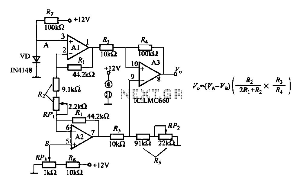
A diode IN4148 temperature circuit is presented. The circuit operates within a temperature range of -25 to 125 degrees Celsius, with an accuracy of 0.5. The core components of the operational amplifier circuit consist of four LMC660 amplifiers. It...
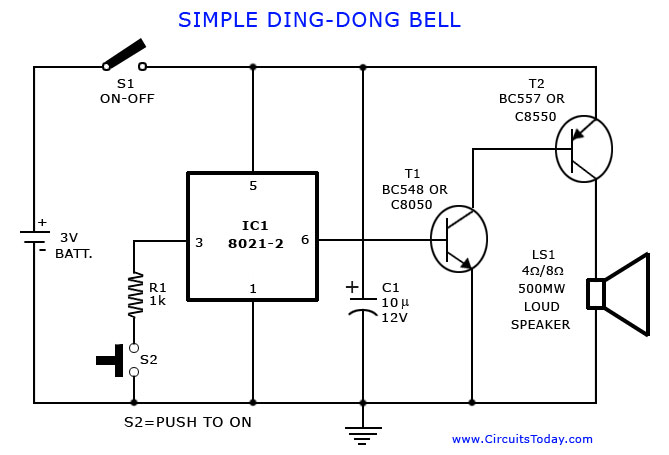
A tone generator circuit, which can be used to create a simple calling bell circuit, is illustrated here. It is constructed using the 8021 integrated circuit (IC), which includes built-in circuitry for producing a "ding-dong" sound. The tone generator circuit...
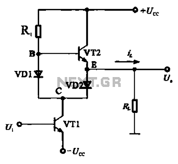
A Class AB output stage circuit is coupled with diodes, as illustrated in Figure 10-8. The static bias circuit for transistor VT1 (not shown) is adjusted so that the output at point E is at ground DC voltage UE....
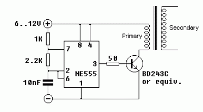
The core component of this circuit is the 555 timer IC. The alert sound does not stop immediately when the switch is activated; instead, it ceases automatically after a predetermined time period, which is set by the resistance of...
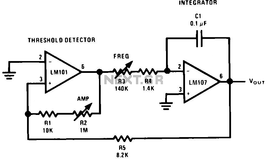
The generator consists of an integrator functioning as a ramp generator and a threshold detector with hysteresis acting as a reset circuit. The integrator has been previously described and does not require further elaboration. The threshold detector operates similarly...
Warning: include(partials/cookie-banner.php): Failed to open stream: Permission denied in /var/www/html/nextgr/view-circuit.php on line 713
Warning: include(): Failed opening 'partials/cookie-banner.php' for inclusion (include_path='.:/usr/share/php') in /var/www/html/nextgr/view-circuit.php on line 713