
Radio receiver circuit for long and medium wave
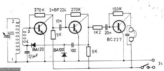
The described oscillating circuit utilizes a ferrite bar as its core, which enhances the inductive properties of the windings. The choice of ferrite material is critical, as it provides the necessary magnetic permeability to optimize the circuit's performance across the desired frequency ranges. The windings "1-2" and "3-4" are configured to create two distinct inductors, allowing the circuit to be tuned for long-wave or medium-wave reception.
For long-wave applications, the winding specifications of 135 turns for "1-2" and 20 turns for "3-4" ensure that the circuit can resonate at lower frequencies, which are typically below 300 kHz. Conversely, the medium-wave configuration, with 75 turns for "1-2" and 7 turns for "3-4", allows for resonance at frequencies typically ranging from 530 kHz to 1700 kHz. The use of CuEm wire with a diameter of 0.15 mm is appropriate for minimizing resistive losses while maintaining adequate flexibility for winding.
The integration of a variable capacitor (40-400 pF) in parallel with winding "1-2" is essential for tuning the circuit. This capacitor allows for fine adjustments to the resonant frequency, enabling the user to select specific stations by varying the capacitance. The presence of high-impedance headphones (1000-2000 ohms) ensures that the circuit can effectively drive the audio signal without loading down the oscillating circuit, which could lead to distortion or loss of signal quality. The additional 10 nF capacitor in parallel with the headphones serves to filter high-frequency noise, providing a clearer audio output.
Overall, this oscillating circuit design is well-suited for amateur radio enthusiasts and provides a practical means of receiving long and medium wave signals with clarity and precision. Proper construction techniques and component selection are crucial for achieving optimal performance and reliability in operation.Oscillating circuit (coil) are made on a ferrite bar. If you wish to listen long waves winding "1-2" has 135 turns and 3-4 has 20 turns. If you wish to receive medium wave winding "1-2" has 75 turns, and "3-4" has 7 turns (wire used must be CuEm 0. 15mm). In parallel with the winding 1-2 is necessary to connect a 40-400pF variable capacitor. Listen ing signal is made using high impedance headphones to 1000-2000 ohms, which have a capacitor of 10nF in parallel. 🔗 External reference
Related Circuits
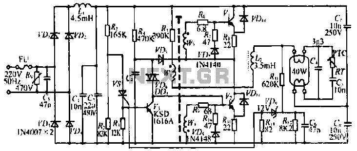
The figure illustrates the input from the varistor, which serves an overvoltage protection role. Components VDi and VD4 function as rectifiers, while L1 and C2 are utilized for filtering. The circuit comprises R, C9, and VD6, which are part...
This project originates from the past and has demonstrated significant success. It serves as the foundation for an 8-channel proportional R/C (AM) and 145MHz FM chat box. The receiver design is straightforward and includes a single transistor mixer followed...
This simple circuit can be utilized to activate various devices, such as microcontrollers, relays, secret alarms, or robot applications. It can also be used to turn on LED1, which remains illuminated as long as the metal plate is touched....
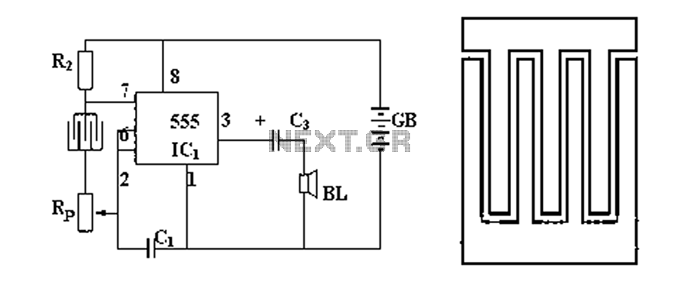
Figure 1 illustrates a circuit diagram related to an audio circuit that incorporates a resistance between two leads connected to a rain alarm probe. Figure 2 demonstrates the connection of a capacitor to the probe within the audio circuit....
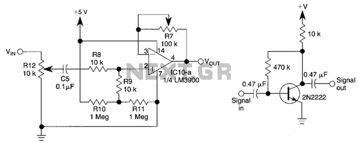
This circuit utilizes one-quarter of an LM3900 to create a simple variable-gain front end for an oscilloscope. R7 serves as the gain control. Additionally, a basic preamplifier is included for applications requiring more than 10X gain. The circuit employs the...
This circuit utilizes the TLC555CP timer integrated circuit to flash an LED approximately twice per second. This specific 555 timer operates on a voltage of only 3 volts, allowing it to be powered by two 1.5-volt cells. When using...