
As current feedback circuit of four b
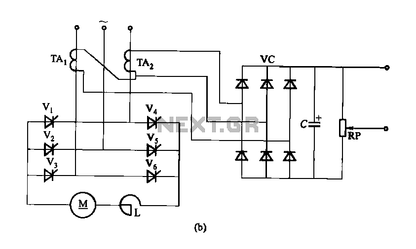
The three-phase rectifier circuit depicted in Figure 16-40 is designed to convert alternating current (AC) from a three-phase supply into direct current (DC). The inclusion of a current cutoff feedback circuit enhances the protection and efficiency of the system by ensuring that the output current remains within safe operational limits.
In part (a), the use of three current transformers allows for precise monitoring of the current flowing through each phase of the rectifier. These transformers provide real-time feedback to the control system, enabling it to adjust the rectification process dynamically. This ensures that any imbalances in the current are detected and corrected promptly, which is critical for maintaining the reliability of the rectifier circuit.
In part (b), the configuration with two current transformers connected in an open delta secondary arrangement offers a more economical solution while still providing effective current monitoring. This setup reduces the number of components required, which can be advantageous in applications where space or budget constraints are a concern. The open delta arrangement allows for the measurement of phase currents while still providing adequate feedback for the control system to function effectively.
Overall, the design of the three-phase rectifier circuit with current cutoff feedback is essential for applications requiring stable and reliable DC power, particularly in industrial environments where three-phase systems are prevalent. The choice between using three individual current transformers versus a pair in an open delta configuration depends on the specific requirements of the application, including factors such as cost, space, and the level of precision needed in current monitoring.Figure 16-40 three-phase rectifier circuit current cutoff feedback circuit. Figure 16-40 (a) use three current transformers; Fig. 16 40 (b) using two connected in open delta se condary current transformer.
Related Circuits
The EQ-2 is a 6-band graphic equalizer circuit. Each band is controlled by potentiometers RV1-6, which are designed as faders for improved visual indication of adjustments. However, standard potentiometers can also be used as replacements. At the center position...
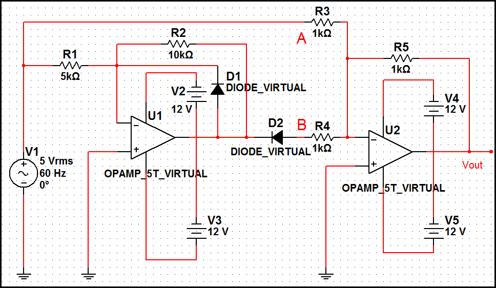
The optimal operational amplifier circuit used to convert a sine waveform into a rectangular waveform is the Schmitt trigger circuit. The Schmitt trigger circuit is a vital component in signal processing, particularly for converting analog signals into digital signals. It...
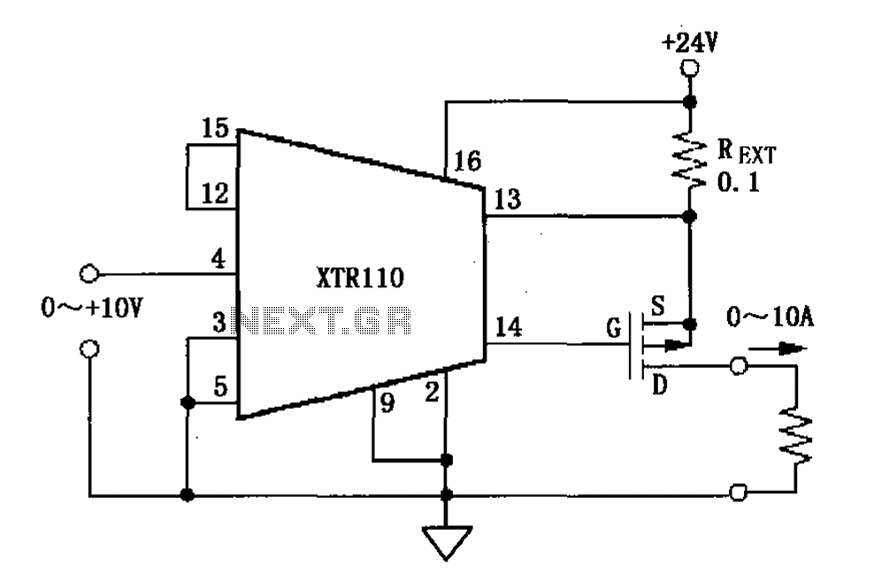
When the output current exceeds 40mA, the XTR110 requires the use of an external resistor (REXT) instead of the internal 50-ohm resistor (R9). REXT should be connected between pin 13 and pin 1. The value of REXT is determined...
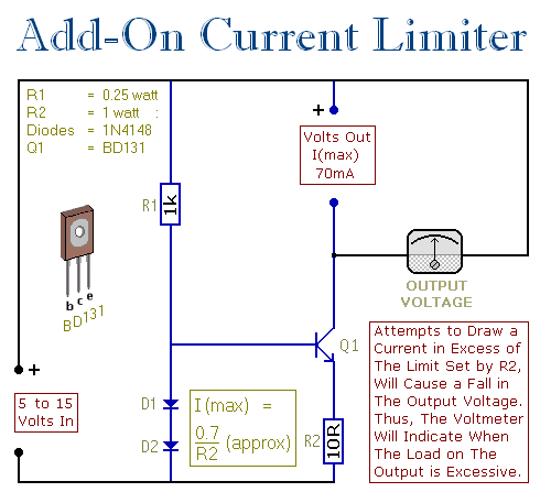
This circuit allows you to set a limit on the maximum output current available from your PSU. It's very useful when you power-up a project for the first time or carry out a soak-test. By setting an upper limit...
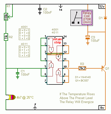
A CMOS 4001 or a CMOS 4011 can be utilized in this circuit, as both contain four two-input gates. The inputs of each gate are connected together, allowing them to function as simple inverters. This means that when both...
As shown in the figure, D187 is a UART with its RX/TX signals connected through optocouplers N21, N22, and N29, providing complete optoelectronic isolation for the RS-485 communication interface receiver/transmitter D28 and microprocessor D211. D197 serves as a generator,...