
Simple Buzzer Using Only Passive Components
The novel buzzer circuit operates by employing a relay to control the flow of current to a small audio transformer, which in turn drives a speaker to produce sound. The relay serves as an electromechanical switch that opens and closes the circuit, allowing for the modulation of audio signals.
The circuit can be described as follows: When a control voltage is applied to the relay's coil, it energizes the relay, closing its normally open contacts. This action allows current to flow through the audio transformer. The transformer steps up or modifies the audio signal, which is then delivered to the speaker. The speaker converts the electrical energy into sound waves, producing the desired buzzing noise.
Key components of the circuit include the relay, which should be selected based on the required voltage and current ratings, ensuring it can handle the load of the audio transformer and speaker. The audio transformer should be chosen to match the impedance of the speaker for optimal sound quality. The speaker itself should have an appropriate power rating to handle the output from the transformer without distortion or damage.
In summary, this simple buzzer circuit effectively demonstrates the use of a relay in conjunction with an audio transformer and speaker to generate sound, making it suitable for various applications such as alarms, notifications, or simple sound effects in electronic projects. Proper selection of components and attention to circuit design will ensure reliable operation and sound performance.This circuit is a simple buzzer circuit and it called novel buzzer. It only uses a relay in series with a small audio transformer and speaker. The relay will. 🔗 External reference
Related Circuits
In the first circuit, the BC548 transistor is configured as a Colpitts oscillator, with the frequency being adjusted through the use of a crystal. A high-quality crystal will produce high-frequency oscillations, and the output at the collector is rectified...
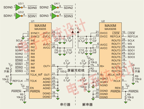
Low Voltage Differential Signaling (LVDS) is an effective digital video signal transmission interface that supports low-cost digital audio data streaming. This article discusses the use of Maxim Integrated Products Inc.'s MAX9205/MAX9206 10-bit LVDS serializer/deserializer (SerDes) to transmit up to...
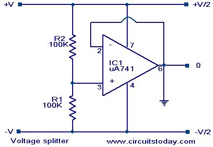
Voltage splitter using op-amp uA741 IC, circuit diagram, working, description. The voltage splitter circuit utilizing the uA741 operational amplifier (op-amp) is designed to provide a stable output voltage that is a fraction of the input voltage. The uA741 is a...
This design features a simple metal detector with commendable characteristics. Its operational principle differs from traditional schemes such as BFO (Beat Frequency Oscillator) and the two-box transmit-receive metal detectors. The dynamic mode is employed to locate targets in environments...
As readers may know, there are several power amplifier projects, including two that utilize integrated circuit (IC) power amplifiers, commonly referred to as power op-amps. Both of these projects have gained popularity, and this new project is not intended...
There are two types of preamplifiers for magnetic phono cartridges. The most common type includes an RIAA equalization network in the feedback loop, as described in the March 2002 issue of SILICON CHIP. The second type, previously used in...
Warning: include(partials/cookie-banner.php): Failed to open stream: Permission denied in /var/www/html/nextgr/view-circuit.php on line 713
Warning: include(): Failed opening 'partials/cookie-banner.php' for inclusion (include_path='.:/usr/share/php') in /var/www/html/nextgr/view-circuit.php on line 713