
Simple Circuit Communicates Over Low-Voltage Power Lines
The circuit utilizes OOK modulation to encode digital data, where the presence of a carrier signal represents a binary '1' and the absence indicates a binary '0'. This method is particularly effective for low-bandwidth applications, as it simplifies the modulation process and allows for efficient use of existing power lines without requiring additional wiring.
The high-frequency carrier is generated by an oscillator circuit, which ensures that the signal remains above the noise floor of the power supply line. Typically, the carrier frequency is chosen to be significantly higher than the fundamental frequency of the power line to minimize interference and ensure reliable data transmission.
At the transmitter side, the data to be sent is fed into the modulator, which combines the data signal with the carrier frequency. This modulated signal is then coupled onto the power line using a coupling capacitor or transformer, depending on the design requirements. The coupling element allows the high-frequency signal to pass while blocking the low-frequency AC power, ensuring that the data does not interfere with the power delivery.
On the receiver side, a demodulation circuit is employed to extract the data from the received modulated signal. This typically involves a band-pass filter that isolates the carrier frequency, followed by a demodulator that converts the OOK signal back into its original digital format. The demodulated data can then be processed or utilized as needed.
Overall, this circuit design provides a practical solution for data transmission over existing infrastructure, reducing the need for additional cabling and simplifying installation in various applications, such as home automation systems, remote monitoring, and industrial control systems.This circuit solves the problem of sending data over a cable with no free conductors. The data is OOK (on-off keying) modulated and superimposed on a high-frequency carrier so it can be sent over a low-voltage power supply line 🔗 External reference
Related Circuits
The following circuit illustrates a 2500W Phase Control Circuit Schematic. Features include a ground-tied trigger output that is disabled, and a low voltage input. The 2500W Phase Control Circuit is designed to regulate the power delivered to a load by...

The multi-purpose signal generator circuit consists of integrated circuit oscillators and frequency dividers. It generates square waves ranging from high frequencies to sub-audio frequencies and also produces a frequency standard in the VHF range. The alternative oscillator section feeds...
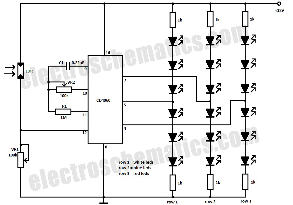
This simple Christmas LED lights decoration circuit allows for the creation of an 18 LED flasher to adorn a Christmas tree. The circuit incorporates white, blue, and red LEDs that flash in a festive pattern. The circuit is designed to...
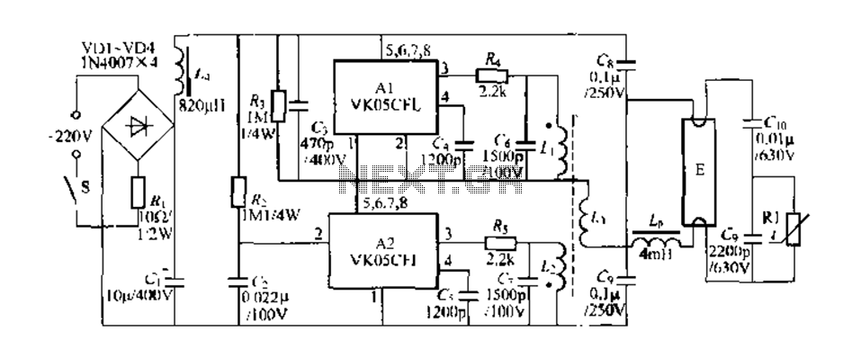
Figure 289 illustrates the VK05CIl, an ASIC produced by STMicroelectronics (ST) designed to operate low-power compact fluorescent lamps ranging from 5 to 15W. The VK05CFI is engineered to drive approximately 23W low-power compact fluorescent lamps using high-pressure composite bipolar...
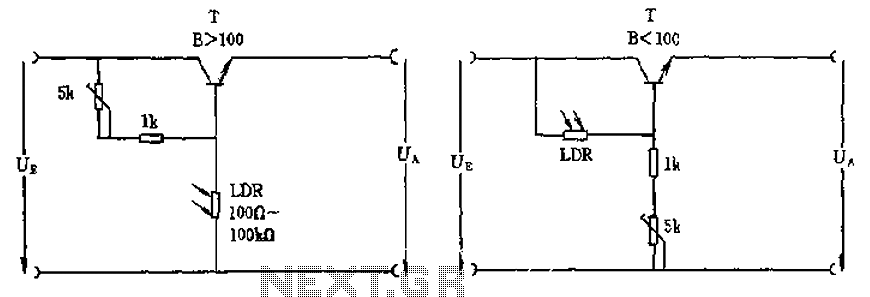
The circuit depicted involves a photoresistor (LDR) connected to a transistor, which operates at either a high or low level based on light conditions. The amplification factor of the transistor is 100, which is adequate for the application. The...
The interval between rings can be adjusted by changing the value of the 1 Meg resistor. A 70 volt, 30 Hz ringing voltage is generated from the 120 volt side of a small 12.6 VAC power transformer (Radio Shack...