
2500W Phase Control Circuit Schematic
The 2500W Phase Control Circuit is designed to regulate the power delivered to a load by controlling the phase angle of the AC waveform. This type of circuit is commonly used in applications such as dimmers for lighting, motor speed controllers, and temperature control in resistive heating elements.
The schematic typically includes several key components: a triac or thyristor for switching, a zero-crossing detector to synchronize the control signal with the AC waveform, and a control circuit that determines the phase angle at which the triac is triggered.
The ground-tied trigger output ensures that the circuit remains stable and prevents false triggering due to noise or fluctuations in the input signal. The low voltage input feature allows the circuit to be controlled by low-power microcontrollers or other low-voltage control devices, enhancing its versatility in various applications.
In practical implementations, it is important to include appropriate snubber circuits across the triac to protect it from voltage transients and to ensure reliable operation. Additionally, heat sinks may be necessary to dissipate heat generated by the triac under high load conditions. Proper design considerations for component ratings, layout, and thermal management are crucial to ensure the reliability and efficiency of the phase control circuit.
This circuit can be utilized in various applications where precise control over power delivery is required, making it a valuable tool in modern electronic design.The following circuit shows about 2500W Phase Control Circuit Schematic. Features: tied to ground trigger output disabled, ow voltage input to .. 🔗 External reference
Related Circuits
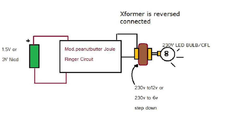
Various threads on ringer circuits have been observed, showcasing multiple variants, particularly concerning the types of transformers utilized, such as air core and step-down transformers. One notable circuit is the 12V-to-120V configuration, which employs a joule ringer that utilizes...
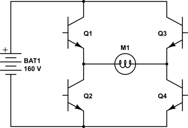
The project involves controlling a single-phase AC induction motor using two IGBTs. One IGBT is designated for switching the PWM signal to the motor, with a fixed PWM frequency of 16 kHz, while the second IGBT is employed for...
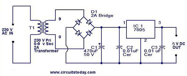
A 5V power supply using IC 7805 is designed and explained with a neat circuit diagram. The circuit for a 5V power supply utilizing the IC 7805 voltage regulator is a straightforward and efficient design that provides a stable output...

This is a circuit for Closed-Loop Automatic Power Control for RF Applications. The circuit utilizes a log detector (AD8318) and a variable gain amplifier (VGA) (ADL5330). The Closed-Loop Automatic Power Control (APC) circuit is designed to maintain a consistent output...
AVC - The circuit regulates the volume line automatically, providing an output voltage of approximately 4 volts peak to peak. This voltage remains consistent. The Automatic Volume Control (AVC) circuit is designed to manage audio levels dynamically, ensuring a stable...
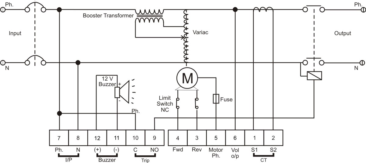
The BPS Servo Controller - Digital is a comprehensive metering and control solution designed for servo stabilizers, accommodating a wide range of input voltages and load requirements. This system minimizes production overheads such as wiring and testing, thereby enhancing...
Warning: include(partials/cookie-banner.php): Failed to open stream: Permission denied in /var/www/html/nextgr/view-circuit.php on line 713
Warning: include(): Failed opening 'partials/cookie-banner.php' for inclusion (include_path='.:/usr/share/php') in /var/www/html/nextgr/view-circuit.php on line 713