
simple common emitter amplifier
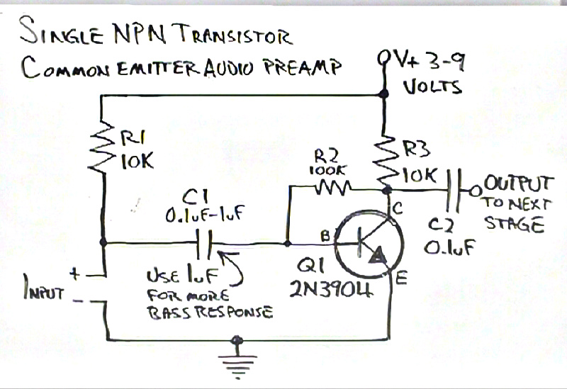
The circuit in question is a common emitter amplifier utilizing an NPN transistor, primarily aimed at amplifying audio signals. The configuration includes a collector feedback mechanism, which enhances stability and linearity in amplification. In this setup, R1 serves a dual purpose: it can provide a DC biasing voltage to the transistor while also influencing the AC signal characteristics. However, its effect on the gain was negligible, as confirmed through simulation.
The capacitor C1 plays a crucial role in AC coupling, blocking any DC component from the signal while allowing AC signals to pass through. This is essential in audio applications to prevent DC offset from affecting downstream components. The removal of R1 indicates that the amplifier can function effectively without it, suggesting that the circuit design can be simplified without compromising performance.
The potential application of the preamp with an electret microphone highlights the need for a proper biasing arrangement to ensure optimal operation of the microphone's internal FET. In scenarios where the microphone is not utilized, the absence of R1 prevents unnecessary power dissipation, thereby enhancing efficiency.
When cascading multiple stages of this amplifier, attention must be given to the DC blocking capacitors and the resistors used for biasing. The design must ensure that each stage operates within its linear region while avoiding excessive power consumption. The inclusion of additional components, such as capacitors and resistors, should be carefully considered to maintain the desired frequency response and minimize signal degradation.
In summary, the examined circuit exemplifies a straightforward yet effective approach to audio amplification, with considerations for biasing and component selection playing pivotal roles in its performance and efficiency.I hadn`t worked through the biasing calculations for collector feedback common emitter amplifiers before, so I thought I`d do that for the simple one transistor NPN preamp that Dino built as his weeklyhack. But even before I got to it, I was confused by something. Check out the schematic (cribbed from Dino`s post): I was confused by R1. It`s only purpose seemed to be to provide a DC offset, which was immediately removed by the action of C1. So, since I had built the circuit in LTSpice, I tried varying its value from 1 ohm to 100MEG ohms, and indeed, it had no effect on the overall gain of the amplifier. So, I removed it entirely. And the circuit continued to work just fine. So, what`s the deal I suspect that R1 was part of a circuit that powered an electret microphone: if the Input on his schematic were an electret microphone, you`d need to provide some voltage into it to power the built in FET preamp ( like you see in the diagrams on the Wikipedia page for electrets ).
If that power is not needed, then all that happens is the current is dissipated by the input as heat. If you cascade two of these in the naive way, you end up a resistor feeding between voltage between two DC blocking transistors, which doesn`t waste a lot of power (no current flows at DC), but you end up with an extra cap and resistor.
🔗 External reference
Related Circuits
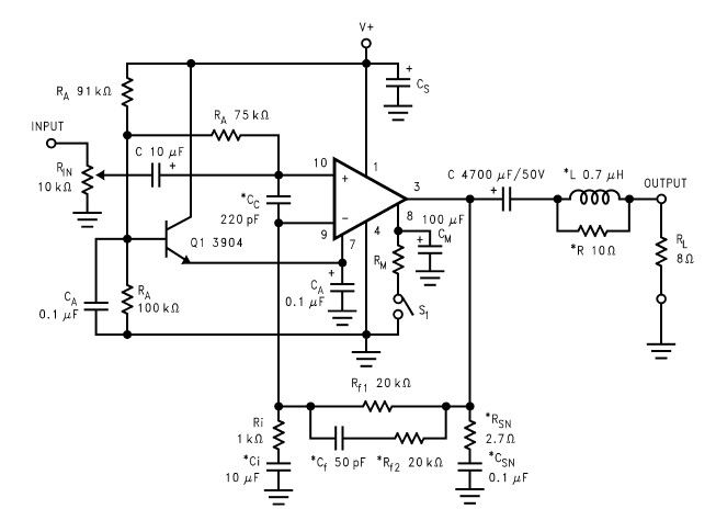
The LM2876 audio power amplifier circuit can be designed as a simple, high-efficiency audio amplifier capable of delivering 40W of continuous average power to an 8-ohm load with a total harmonic distortion plus noise (THD+N) of 0.1% from 20Hz...
The gain of the low-cost IC is internally fixed at no less than 34 dB (50 times). A unique input stage allows input signals to be referenced to ground. The output is automatically self-centering to one-half the supply voltage...
By adding only a few components, a temperature- and beta-compensated current sink can be converted into a common-emitter (CE) amplifier that maintains a stable biased operating point. This design concept will demonstrate the process. To implement this design, the primary...
The AD8221 is an ideal choice for bridge measurement applications due to its low offset voltage and high common-mode rejection ratio (CMRR) across a wide frequency range. The bridge can be directly connected to the device. The AD8221 is an...
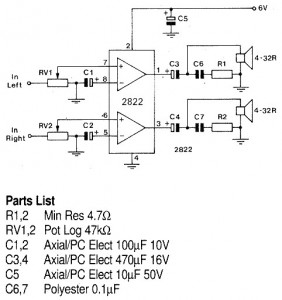
A 1W stereo headphone amplifier circuit, based on the TDA2822, is designed for portable players, radios, and other electronic devices that utilize headphones as the output. The TDA2822 is a dual audio power amplifier IC capable of delivering up to...
Adapting a failed Tesla coil into a crystal radio set for demonstration purposes has presented challenges, particularly with antenna size for optimal signal reception. It has been noted that an ideal AM antenna should range between 100 to 500...
Warning: include(partials/cookie-banner.php): Failed to open stream: Permission denied in /var/www/html/nextgr/view-circuit.php on line 713
Warning: include(): Failed opening 'partials/cookie-banner.php' for inclusion (include_path='.:/usr/share/php') in /var/www/html/nextgr/view-circuit.php on line 713