Simple continuity tester for pcbs

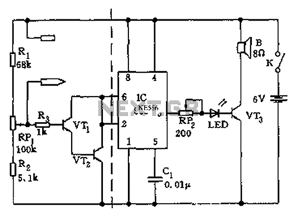
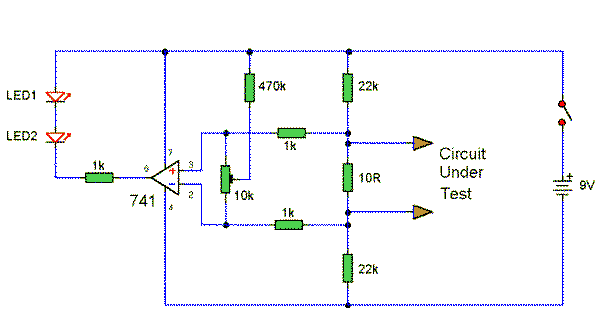
This tester is designed for tracing wiring on Printed Circuit Boards (PCBs). Resistors below 50 ohms function as a short circuit, while those above 100 ohms behave as an open circuit. The circuit comprises a simple multivibrator activated by transistor T3. The components connected to the base of T3 include D1, R1, R2, and the test resistance. Additionally, with a 1.5-volt supply, there is inadequate voltage to activate a semiconductor connected to the test terminals.
The circuit operates as a basic continuity tester for PCBs, utilizing a multivibrator configuration to provide a visual or audible indication of circuit continuity. The multivibrator is triggered by the state of the resistance at the test terminals. When a resistor below 50 ohms is connected, the circuit recognizes this as a short circuit, allowing the multivibrator to oscillate, which can be indicated by an LED or a buzzer. Conversely, if the resistance exceeds 100 ohms, the circuit interprets this as an open circuit, resulting in no oscillation.
Transistor T3 acts as a switch, controlling the multivibrator's operation based on the input from the test resistance. The components D1 (likely a diode), R1, and R2 are configured to set the biasing conditions for T3, ensuring that it operates effectively within its active region. The diode D1 may serve to protect the circuit from reverse polarity or to shape the waveform generated by the multivibrator.
The limitation of a 1.5-volt supply indicates that the circuit is designed for low-power applications, suitable for handheld or portable testing devices. However, due to the low voltage, it may not be capable of activating certain semiconductor devices connected to the test terminals, which could require a higher threshold voltage to operate effectively. This aspect should be considered when using the tester in various applications, as it may limit its versatility in testing different components on the PCB.This tester is for tracing wiring on Printed Circuit Boards. Resistors below 50 ohms act as a short circuit; above 100 ohms as an open circuit. The circuit is a simple multivibrator switched on by transistor T3. The components in the base of T3 are Dl, Rl, R2, and the test resistance. With a 1,5 volt supply, there is insufficient voltage to turn on a semiconductor connected to the test terminals.
