
Simple Metal Detector

On the Schematic, I show Two Possible Coils.
1) The Ferrite Rod, creates an Accurate Pin Point. But it also has a Very Narrow Detection Field.
2) The Dual Wound "Tesla Coil" Creates a Wide Field of Detection. With Maximum Sensitivity at the Center of the coil.
Detection of metal is with a Meter and LED. The Meter Gives a Much Better Sensitivity. More: On My Prototype, I can detect a 1/8 Gram Gold Nugget at One Inch, With Either the Tesla Coil or the Larger Ferrite rod coil. But Only about 1/2 inch with the Tiny Ferrite rod one.
Changes to capacitor "CX" will change the Operating Frequency. It may also Improve Sensitivity.
I Recommend Expermenting with Different "CX" Caps and also Various types of coils. The Tesla Coil has an ID of 1" and an OD of 4 3/8". And Each Coil has an Inductance of 150uH. Using this coil In my Test Circuit, CX is .01uF.
On This Ferrite Rod, Coil "A" is 600uH. And Coil "B" is 100uH. Here I used a Ferrite Rod, Made by "FairRite".
I had to Increase the Coarse trimpot to 10K to get it to Oscillate. But it than worked OK. Here I used a Tiny 3/16 dia Ferrite Rod, I bought on-line. Specifications Unknown.
The circuit described involves a metal detection system that utilizes two types of coils: a Ferrite Rod coil and a Dual Wound Tesla Coil. The Ferrite Rod coil is noted for its ability to create an accurate pin-point detection but has a narrow detection field, making it suitable for precise applications. In contrast, the Tesla Coil offers a wider detection field with maximum sensitivity at its center, making it ideal for broader detection tasks.
The detection mechanism employs a meter and an LED indicator to provide visual feedback on the presence of metal. The meter enhances sensitivity, allowing for the detection of small gold nuggets, such as a 1/8 gram nugget at a distance of one inch when using either the Tesla Coil or the larger Ferrite Rod coil. However, the smaller Ferrite Rod coil is limited to detecting at approximately half an inch.
The operating frequency of the circuit can be modified by changing the capacitor labeled "CX," which may also lead to improvements in sensitivity. Experimentation with various capacitor values and coil types is encouraged to optimize performance. The specifications for the Tesla Coil include an inner diameter (ID) of 1 inch, an outer diameter (OD) of 4 3/8 inches, and an inductance of 150 microhenries (µH). In a test circuit, a capacitor value of 0.01 microfarads (µF) is used.
For the Ferrite Rod, two distinct coils are mentioned: Coil "A" with an inductance of 600 µH and Coil "B" with an inductance of 100 µH, both made by FairRite. The circuit design required an adjustment to the coarse trimpot, which was increased to 10K ohms to achieve oscillation, indicating that the circuit operates in a feedback loop typical of metal detection systems. The use of a small 3/16 inch diameter Ferrite Rod is noted, although its specifications remain unspecified.The Meter and other small circuit differences, gives better performance. On the Schematic, I show Two Possible Coils. 1) The Ferrite Rod, creates an Accurate Pin Point. But it also has a Very Narrow Detection Field. 2) The Dual Wound "Tesla Coil" Creates a Wide Field of Detection. With Maximum Sensitivity at the Center of the coil. Detection of metal is with a Meter and LED. The Meter Gives a Much Better Sensitivity. On My Prototype, I can detect a 1/8 Gram Gold Nugget at One Inch, With Either the Tesla Coil or the Larger Ferrite rod coil. But Only about 1/2 inch with the Tiny Ferrite rod one. Changes to capacitor "CX" will change the Operating Frequency. It may also Improve Sensitivity. I Recommend Expermenting with Different "CX" Caps and also Various types of coils. The Tesla Coil has an ID of 1" and an OD of 4 3/8". And Each Coil has an Inductance of 150uH. Using this coil In my Test Circuit, CX is .01uF. On This Ferrite Rod, Coil "A" is 600uH. And Coil "B" is 100uH. Here I used a Ferrite Rod, Made by "FairRite" I had to Increase the Coarse trimpot to 10K to get it to Oscillate.
But it than worked OK. Here I used a Tiny 3/16 dia Ferrite Rod, I bought on-line. Specifications Unknown. 🔗 External reference
Related Circuits
The core component of this DIY metal detector circuit is the CS209A integrated circuit (IC). The metal detector is constructed using a single 100µH coil, which has a diameter of 40 mm. The CS209A IC serves as the primary signal...
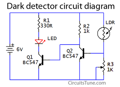
This is a basic dark detector or sensor circuit diagram based on a photoresistor (LDR) and a few components. The dark detector circuit utilizes a photoresistor (LDR) as the primary sensing element. The LDR is a light-dependent resistor that changes...
This circuit is a simple analog multiplier. The operation of the circuit can be understood by considering A2 as a controlled gain amplifier that amplifies V2, with its gain dependent on the ratio of the resistance of PC2 to...
With the advent of modern integrated circuits (ICs), sophisticated circuits today are no longer required to be complex and lengthy. The chips themselves contain most of the intricate circuitry built-in and can independently perform the desired functions. For instance,...
The circuit is capable of enhancing the system power factor to a value exceeding 0.99. It effectively reduces the waveform distortion of the input supply current, ensuring compliance with GB15144 standards, with a distortion index lower than level L....
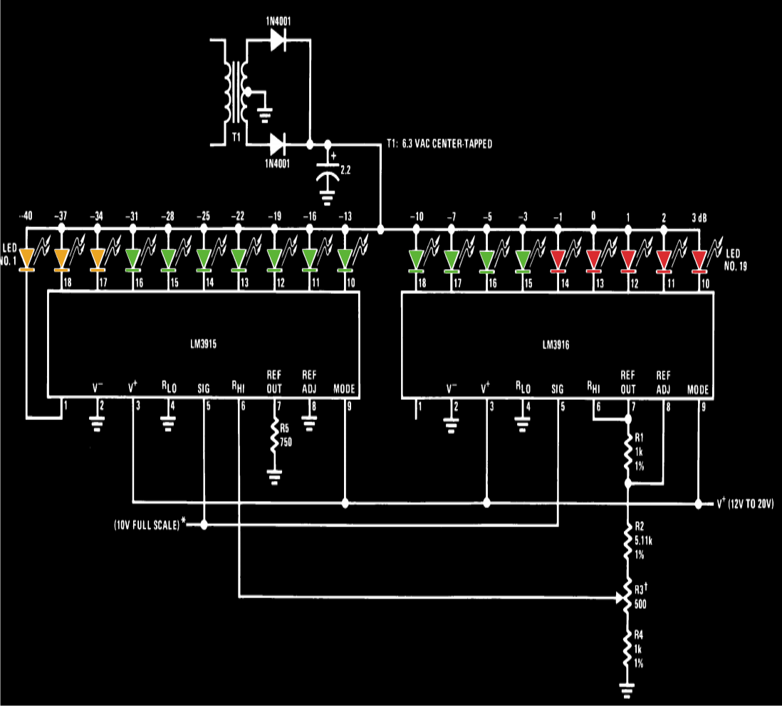
A VU meter, or volume unit meter, is a device used to indicate the music volume output from an amplifier or loudspeaker system. It can also be viewed as a device for displaying the PMPO (Peak Music Power Output)...