
Simple Curve Tracer Circuit

The EZ-Curve is an essential tool for electronic experimentation, providing a visual representation of the electrical characteristics of various two-terminal devices. It is particularly valuable for analyzing components such as diodes, transistors, triacs, SCRs, resistors, and LEDs. The operation of the curve tracer is based on the principle of passing current-limited AC signals through the device under test (DUT) while simultaneously measuring the voltage across it and the current flowing through it.
The circuit typically consists of a signal generator that produces a sine wave or triangular waveform, which is fed into the DUT. A precision resistor is placed in series with the DUT to ensure accurate current measurement. The voltage across the DUT and the precision resistor is monitored, allowing for the calculation of both current and voltage values. These measurements are then displayed on an oscilloscope, which plots the volt-ampere characteristic curve of the device.
The oscilloscope provides a graphical representation of the relationship between voltage and current, facilitating the identification of key parameters such as forward voltage drop, reverse breakdown voltage, and dynamic resistance. This information is crucial for understanding the behavior of the device under various operating conditions.
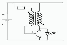
In summary, the EZ-Curve curve tracer is a versatile and practical instrument for electronics laboratories, enabling users to conduct detailed analyses of a wide range of electronic components efficiently. Useful for checking diodes, transistors, triacs, SCRs, resistors, and LEDs, this curve tracer should prove useful in the experimenter`s lab. It displays the volt-ampere characteristic of a two-ter-minal device on an oscilloscope. This is a simple block diagram of the EZ-Curve. Current-limited AC signals are passed through both the device under test and a precision resistor to yield current and voltage readings.
Related Circuits
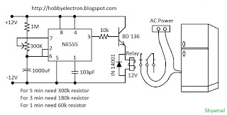
A 5-minute circuit can continue to operate during a power outage, providing protection for the refrigerator. The refrigerator power protection circuit, designated as 1136, includes a power transformer that converts 220V voltage through a rectifier bridge (VD1). This setup...
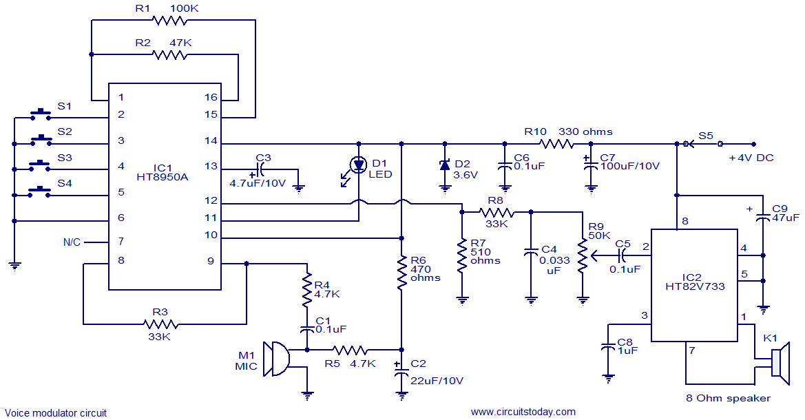
This is a versatile voice modulator circuit utilizing the HT8950A IC from Holtek Semiconductors. The IC can generate seven upward or downward frequency steps based on the input voice at a rate of 8 Hz. Additionally, it features two...
There is a requirement for a compact flashlight to illuminate small text on integrated circuits (ICs) and provide better visibility when examining disassembled components. The flashlight should have a long battery life while avoiding excessive battery consumption, such as...
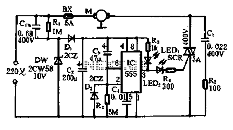
This is a simple freeze protector circuit diagram, also known as a timing circuit. It serves as a hobby project for beginners. This circuit can automatically operate any device after a fixed time once AC power supply is restored....

This 555 timer circuit temperature monitoring system project can monitor temperature at up to four points. The system allows for the selection of whether the alarm should be triggered when the temperature increases or decreases, depending on the resistance...

This design circuit functions as a sine wave oscillator, providing both sine and square wave outputs across a frequency range from below 20 Hz to above 20 KHz. The oscillation frequency can be easily adjusted by varying a single...