
555 timer circuit temperature monitoring system

The 555 timer temperature monitoring system utilizes a combination of resistive temperature sensors, a potentiometer for reference setting, and a relay for alarm activation. The NTC thermistor (R9) serves as the primary temperature sensor, exhibiting a decrease in resistance as temperature rises. This behavior is critical for the functionality of the circuit, as it directly influences the voltage levels at the inputs of the operational amplifier (IC2).
The operational amplifier is configured to compare the voltage from the thermistor against a reference voltage set by the adjustable potentiometer (P1). The configuration of R10 determines the alarm triggering conditions. When R10 connects the positive supply to output 6 of IC2, the system is set to trigger the alarm on temperature increases. Conversely, connecting R10 to ground allows the system to trigger an alarm when the temperature decreases below the set reference value.
When the output of IC2 transitions due to the temperature changes, it controls the relay, which is rated to handle a load current of about 20 mA. This current is sufficient to activate the relay, allowing it to close the circuit and sound the alarm. The transistor (T1) acts as a switch, amplifying the control signal from the operational amplifier to drive the relay.
The astable multivibrator configuration of the 555 timer provides a continuous square wave output, which could potentially be used for periodic monitoring or as a sound signal for the alarm. The frequency of approximately 4 kHz ensures that the alarm sound is perceptible, alerting users effectively to temperature deviations.
Overall, this temperature monitoring system is versatile, allowing for configurations based on specific monitoring needs, whether for high or low-temperature alarms, making it suitable for various applications in environmental monitoring, HVAC systems, or any scenario requiring temperature oversight.This 555 timer circuit temperature monitoring system electronic project can be monitor temperature in up to four points. Using this 555 timer circuit temperature monitoring system electronic project can be choose if the alarm should be triggered when temperature is increased or decreased.
This depends on the resistance R10. If you connect R10 betw een positive supply conductor and output 6 of IC2 then circuit sound the alarm when the temperature rise over the reference temperature. The reference temperature is set by potentiometer P1. Measured temperature is monitored by NTC resistance R9. Its value decreases when temperature increases, as a result, the voltage at the inverting input is greater than the noninverting input, IC2`s output so provide a void potential.
Temperature relay now absorbs a current of about 20 mA. It is so great that the resistance R1 appear a voltage of 0. 65 V enough to pass transistor T1 in conduction state and trigger the alarm sound. If you want to lower temperature alarm trigger, then resistance R10 should be connected between the output 6 (IC2) and ground. If the monitored temperature falls below the adjusted to the reference value, then the NTC resistance R9 increases.
Inverting input of IC2 becomes more negative, so positive potential output increases. Now take the relay of the temperature again 20 mA current T1 alarm triggers. Timer circuit 555 is connected as astabil multivibrator which produces a frequency of about 4 kHz 🔗 External reference
Related Circuits
This circuit allows users to determine whether a specific point in the circuit is at a positive or negative voltage. It is an inexpensive circuit that utilizes minimal components, making it suitable for use in automobiles or motorcycles. The...

The circuit diagram is designed for precise control of DC motors. It converts DC voltage into a series of pulses, where the duration of each pulse... The circuit utilizes a pulse-width modulation (PWM) technique to regulate the speed and torque...
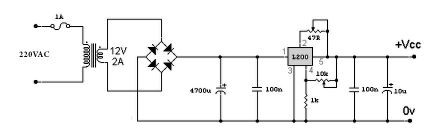
A variable power supply based on the L200 IC, where the output voltage is controlled by a 10K variable resistor. The output voltage ranges from approximately 3 to 15 volts, with a current output ranging from a minimum of...

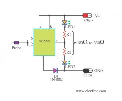
The circuit consists of two main sections: a charger power supply and an LED driver. The charger power supply is designed using a 3-terminal adjustable regulator (IC1) LM317, while the LED driver is based on a BD140 transistor (T2)....
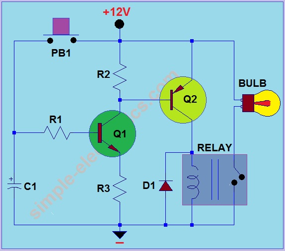
This circuit operates by activating a headlight when the push-button PB1 is pressed. The headlight remains illuminated for a predetermined duration, which can range from several seconds to minutes, before automatically turning off. When PB1 is engaged, capacitor C1...
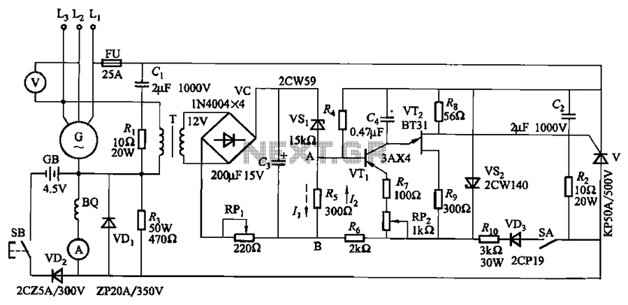
The circuit depicted in Figure 7-32 is designed for an excitation device capable of handling a terminal voltage of 400V and a capacity of less than 75kW for synchronous generator motors, enabling automatic adjustment of excitation. When the generator...