
simple field strength meter
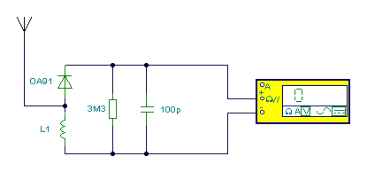
In the context of a VHF receiver circuit designed for the UK FM band, the configuration of the circuit is critical for optimal performance. The use of a digital multimeter set to the lowest DC volts range enables precise voltage measurements, which is essential for tuning the receiver to the desired frequency. By utilizing a 200mV DC range, the multimeter can detect small voltage changes that indicate signal strength variations, thereby allowing for fine-tuning of the circuit.
The inductor L1 plays a pivotal role in the circuit's functionality. The choice of 7 turns on a quarter-inch former with a ferrite slug is significant, as it enhances the inductance and improves the circuit's ability to resonate at VHF frequencies. This design choice ensures that the circuit is well-suited for receiving signals within the UK FM band, which typically ranges from 87.5 to 108.0 MHz.
The high impedance of the digital multimeter is particularly advantageous in this application. With an impedance of approximately 10 Megohms per volt, the meter does not significantly load the tank circuit, preserving the integrity of the signal being measured. This characteristic is vital in RF applications, where loading can lead to inaccurate readings and degraded performance.
Furthermore, the ability of the digital multimeter to detect minute changes in signal strength enhances the user's capability to identify optimal tuning points. This is especially helpful in scenarios where signals may be weak or subject to interference. The improved linearity of the digital meter allows for consistent and reliable readings across a range of signal strengths, facilitating a more accurate assessment of the circuit's performance.
In summary, the combination of a carefully designed inductor, a high-impedance digital multimeter, and the specific tuning practices employed in this VHF receiver circuit contributes to its effectiveness in capturing and analyzing signals within the UK FM broadcasting spectrum.The multimeter should be set to the lowest dc volts range for maximum sensitivity. This is normally 200mV DC for most meters. The circuit works well at VHF (around 100MHz) and was quite pleased with the results. L1 was 7 turns on a quarter inch former with ferrite slug. This covered the UK FM band. A digital multimeter, as opposed to an analogue s ignal meter offers several advantages in this circuit. First, the impedance of a digital meter is very high, around 10Meg/Volt on most meters. This does not shunt the tank circuit unduly. Second, compared to an analogue meter, very slight differences in signal strength can be more easily observed. Thirdly, a digital meter will have better linearity, responding well to both weak and stronger signals.
🔗 External reference
Related Circuits

The following circuit illustrates a Field Strength Meter Circuit Diagram. Features: it is useful for radio frequency hobbyists and enthusiasts, and it uses only... The Field Strength Meter circuit is designed to measure the strength of radio frequency (RF) signals...
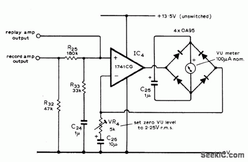
This circuit is utilized in high-quality stereo cassette decks that operate from either an AC line or battery power. It features a meter rectifier bridge integrated into the feedback loop of an operational amplifier (op-amp), which allows for highly...
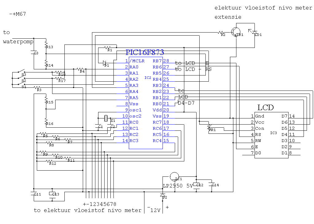
IC4 serves as a counter and oscillator combination, which is the pivotal component of the circuit. The oscillator generates an AC signal that is output on pin 7. This signal is routed through a voltage divider composed of resistors...
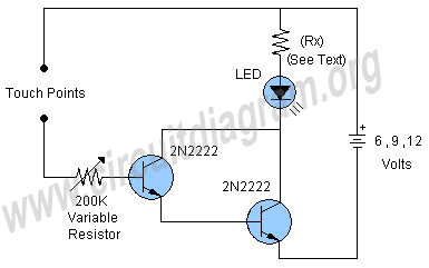
This project involves a simple touch switch circuit that can also be utilized to activate a relay instead of an LED and resistor. The circuit exhibits high sensitivity due to the use of two transistors configured as a Darlington...
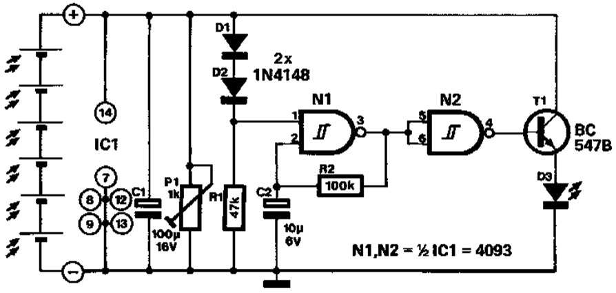
A novel application of solar cells simplifies the process of positioning a car in a garage, offering an improvement over traditional methods such as using old tires, mirrors, or chalk marks. The six solar cells depicted in Figure 1...
Audio metering is prevalent in various devices that play or record audio, ranging from cell phones displaying bar graphs of audio output levels to home stereos with flashing LEDs and live broadcasting equipment. Multiple standards exist for audio metering,...