
Simple digital frequency meter
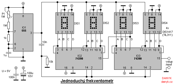
The digital frequency meter circuit operates on the principles of counting pulses generated by an oscillator and displaying the count on a digital readout. The core component, the 74HC390 dual decimal counter, counts the pulses produced by the 555 timer configured as an astable multivibrator. The output frequency of the 555 timer sets the counting period, and the counter increments with each pulse. The selected display (DIS1417 or TIL311) is driven directly by the counter outputs, which are latched to ensure stable readings during the display refresh cycle.
In operation, the circuit begins counting when the output of the 555 timer goes high. This high state lasts for one second, allowing the counter to accumulate the number of pulses. The transition to a low state triggers the display refresh process. At this point, the LATCH feature is disabled, allowing the current count to be transferred to the display. Following this, the counter resets, preparing for the next counting cycle.
The frequency measurement range of 0 to 9999 Hz is determined by the design of the counter and the timing elements of the 555 timer. The resolution can be adjusted by altering the timing interval; shorter intervals allow for higher frequency measurements but may compromise readability due to rapid refresh rates.
For applications requiring higher accuracy, substituting the 555 timer with a crystal oscillator can significantly improve measurement precision. The adjustment of the meter is facilitated by a trimmer potentiometer (P1), enabling calibration against a known frequency source to ensure accurate readings.
This frequency meter design is particularly beneficial for educational purposes or as a low-cost alternative for frequency measurement in various electronic applications.Simple digital frequency meter has many applications. It may be an experiment for beginners, laboratory equipment or a meter built into some device. Ideal wherever there is a need to measure and digitally display the frequency. Circuit The frequency meter is built only from common components (logic), without a microproc essor (microcontroller) that have to be programmed. The basis is 74390 double decimal counter (74HC390 - CMOS, 74LS390 - bipolar). Oscillator with IO1 (555) determines the time of counting. With the component values listed in the schematic diagram below, the counting time is 1s. Frequency meter therefore measures with a resolution of 1Hz. The displays are DIS1417 or TIL311. They have already built LATCH circuits and decoders from BCD to 7 segments. This eliminates the need to use external ones. If you would like to use the standard 7-segment display, it would be necessary to use external LATCH (eg 4-bit 7475 / 74HC75 / 74LS75 8-bit or 74373) and decoders (eg 7447 or 4543). Circuit 555 (IO1) produces rectangular signal at its output (pin 3) staying in log 1 for 1 second, followed by a short pulse of log 0.
During log 1 the counters counts, during the negative pulse are the data on displays refreshed and counters are reset. This is done in two steps: At the falling edge the LATCH feature is turned off and the values in the counters are transmitter to the displays, and the rising edge of the counter then resets the counters to be prepared for next counting cycle.
Frequency meter on the schematic measures in the range 0 to 9999 Hz with a resolution of 1 Hz. However, any number of digits can be chosen and also you can choose different measurement periods. If we choose as 0. 1 s, it will measure up to 99. 99 kHz with a resolution of 10 Hz. If we choose 0. 01 s, frequency meter will measure the frequency up to 999. 9 kHz with a resolution of 100Hz. When we choose a shorter counting interval it is appropriate to extend the log 0 to reduce the refresh rate. If the display refreshs 10x or even 100x per second, the value can unreadable during measurement of variating frequency.
The advantage of controlling the measuring time with RC oscillator with 555 circuit is its simplicity. The disadvantage is a slightly worse accuracy. For more accurate measurements the crystal oscillator can be used. Adjustment: The adjustment of the frequency meter is simple. Hook it to a power supply (about 5V) and connect known input frequency. Then set the trimmer P1 to display the correct value. 🔗 External reference
Related Circuits
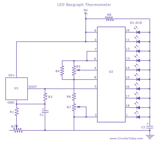
An LED thermometer that can function as a temperature sensor or temperature measurement circuit, utilizing the LM34 for Fahrenheit display or the LM35 for degree Celsius display. The LED thermometer circuit is designed to provide accurate temperature readings using either...
Many analog ohm meters have a non-linear scale, which results in poorer resolution at higher resistance values. This is due to the use of inexpensive current sources. Many analog ohm meters operate on a principle where the scale is not...
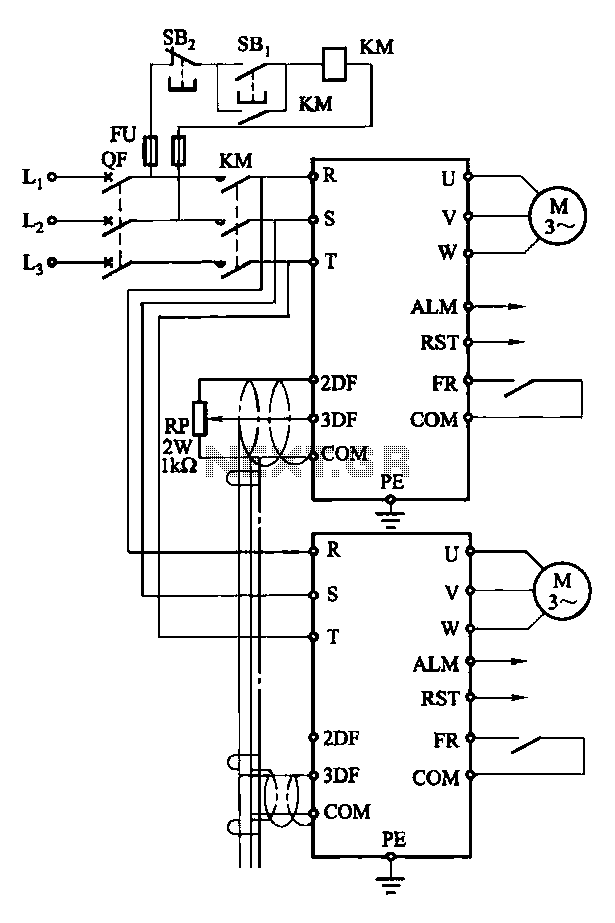
Each motor operates with an independent drive; however, only one frequency is utilized for a specific device. This setup employs a single RP potentiometer to control multiple motors in parallel. In this configuration, the circuit design allows for multiple motors to...
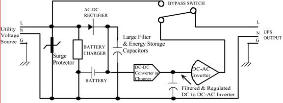
Thomas Edison developed the incandescent light bulb, which operated from a 110-volt DC source. The primary drawback of DC power was that it could only be distributed over short distances without needing to be regenerated. In the early 1900s,...
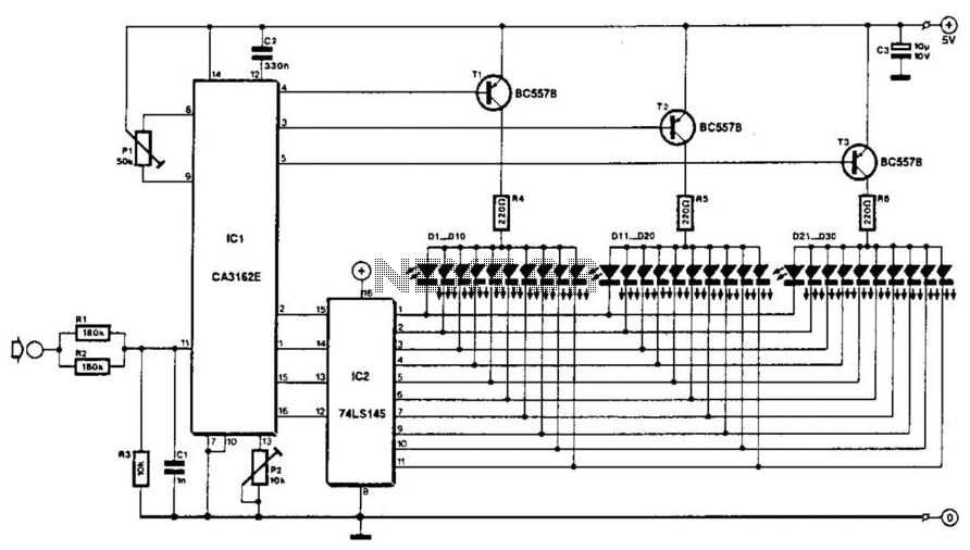
The voltage to be measured is digitized in an analog-to-digital (A/D) converter and then displayed in three decimal digits. The display consists of three groups of 10 LEDs. The meter can only be used for measuring direct voltages. The...
This circuit decomposes an input voltage signal into two components: (1) the absolute value and (2) the polarity or sign (+ or -). It is capable of handling direct input voltages as well as alternating voltages up to several...