
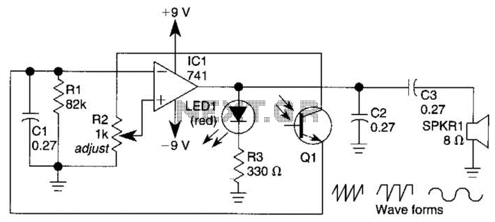
Simple Discrete Logic Probe
The logic probe circuit is a fundamental tool in electronics, serving to indicate the logical state of a digital signal at various points within a circuit. The circuit typically consists of a few key components: a power supply, a resistor, a diode, and an LED (Light Emitting Diode).
When the probe tip is connected to a point in the circuit, the circuit must be powered. If the point is at a high state (usually representing a logical '1'), the voltage at that point will exceed a certain threshold, allowing current to flow through the circuit. This current passes through the resistor and the LED, causing the LED to illuminate, indicating a high state.
Conversely, if the point is at a low state (representing a logical '0'), the voltage will be insufficient to forward bias the diode, and the LED will remain off, indicating a low state.
To enhance the functionality of the logic probe, additional features can be integrated. These may include a built-in buzzer that sounds when a high state is detected or a switch that allows the user to select between different voltage thresholds for testing. The design may also incorporate a multi-colored LED to provide more intuitive feedback, such as green for high and red for low.
The logic probe circuit is essential for troubleshooting and verifying the operation of digital circuits, making it an invaluable tool for engineers and hobbyists alike. Proper understanding and implementation of this circuit can aid in the efficient diagnosis of circuit issues, ensuring reliable performance in electronic systems.This is simple logic probe circuit. Logic probe is used to determine if a point in a circuit has high or low state when the circuit is in operation.? Here is. 🔗 External reference
Related Circuits
A 555 timer operating in astable mode generates driving pulses, while two 4518 dual BCD (binary coded decimal) counters provide square waves. A TL081 operational amplifier functions as an output buffer-amplifier. Potentiometers R1 and R2 are utilized to control...
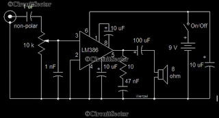
This is a simple low-power audio amplifier circuit capable of producing a power output of 1W. The mono amplifier circuit is built around the LM386 integrated circuit, which operates effectively at low voltages, even below 9V. This low-voltage amplifier...

This logic probe features four channels and employs two quad comparator integrated circuits to drive four bicolor LEDs. The SI and SIB pins are used to set the comparator trip levels for TTL and CMOS logic families. Resistors R6...
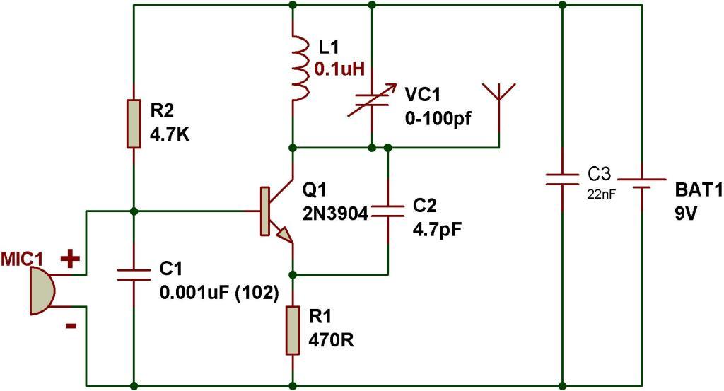
This tutorial outlines the construction of a simple FM transmitter utilizing a single transistor. The project requires minimal components, making it suitable for beginners. Before proceeding, refer to the schematic provided below, which details the components necessary for building...

The following circuit illustrates a Simple Moisture Detector Circuit Diagram. This circuit is based on the 4093 IC. Features include the ability to detect a certain level of moisture. The Simple Moisture Detector Circuit utilizes the 4093 integrated circuit, which...
This circuit is appropriate for any scenario where over-current protection is necessary. An example from the model train hobbyist community illustrates its importance. Experienced model train enthusiasts understand that locating the source of a short circuit can be quite...