
4-Way Logic Probe

This logic probe is designed to provide a visual indication of digital signal levels across four separate channels, making it a versatile tool for troubleshooting and analyzing digital circuits. The use of quad comparators allows for efficient signal processing, enabling the probe to accurately interpret and display the state of the input signals.
The configuration of the SI and SIB pins allows the user to adjust the threshold levels for detecting logic high and low states, accommodating both TTL (Transistor-Transistor Logic) and CMOS (Complementary Metal-Oxide-Semiconductor) technologies. This flexibility is essential for users who work with various digital logic families, as it ensures compatibility and accurate readings.
The biasing resistors R6 through R13 play a critical role in the operation of the logic probe. By preventing false high indications in the presence of open circuits, these resistors enhance the reliability of the probe's readings. This feature is particularly important in circuit debugging, where open connections can lead to misleading diagnostics.
The bicolor LEDs provide immediate visual feedback on the state of the input signals. The distinct colors for high and low states, along with the capability to display intermediate colors for pulsing signals, allow users to quickly assess signal activity. The specification of a duty cycle between 30% and 70% for pulsing signals ensures that the probe can effectively represent varying signal conditions, making it suitable for real-time monitoring of digital waveforms.
Overall, this logic probe is an essential instrument for electronics engineers and technicians, providing a straightforward and effective means of visualizing digital signals across multiple channels. Its design considerations ensure accurate, reliable performance in a variety of applications, from basic circuit testing to more complex digital system diagnostics. This logic probe has four channels and uses two IF quad comparators to drive four bicolor LEDs. SI and SIB program the co mparator trip levels for TTL and CMOS. R6 through R13 bias the probe inputs to prevent the probe from indicating a high for an open circuit. An open circuit will produce an off indication on the LED. The LEDs will indicate one color for high, the other color for low, and intermediate colors for pulsing (assuming a duty cycle between 30 and 70%).
The color that corresponds to high or low depends on how you connect the LEDs. 🔗 External reference
Related Circuits
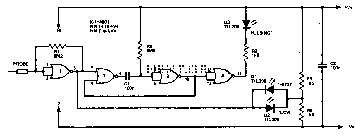
The logic probe can indicate four input states, as follows: floating input - all LEDs off; logic 0 input - D2 switched on (D3 will briefly flash on); logic 1 input - D1 switched on; pulsing input - D3...

The schematic below illustrates four methods of controlling a relay with a digital logic signal. Figure A can be used in most cases where the relay coil requires 100 mA or less and the input current is 2 milliamps...
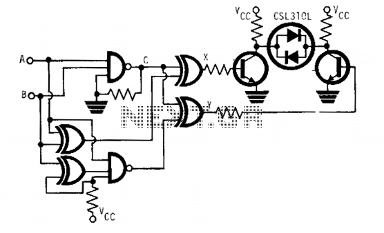
The CSL310L is a dual-color LED that incorporates a red LED and a green LED arranged back to back within a single housing. This LED can emit either red or green light depending on the polarity of the applied...
U20 is a 556 timer configured as a one-shot multivibrator. The output pulse width is determined by the values of R34 and C24, calculated as Pulse width = 1.1 x R34 x C24, resulting in a duration of 0.5...
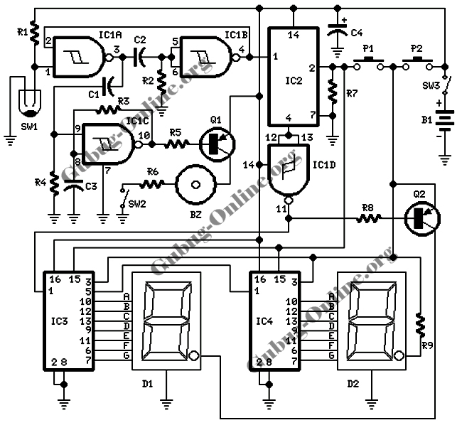
This design features a signal logic tester that utilizes a common cathode seven-segment display. The display indicates a logic level "1" (represented by an "H" on the display) or a logic level "0" (represented by an "L" on the...
This tester, the logic level digital signals indicate on a 7-segment display. The display shows an H as the input signal is high. When the signal is low, the display shows an L on. If the input is open,...